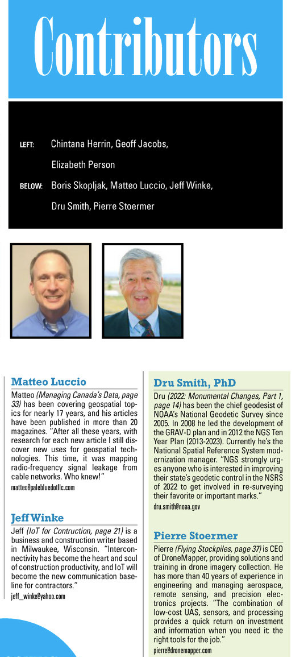
Pierre Stoermer, CEO – DroneMapper.com
xyHt Magazine: http://xyht.com
xyHt December Issue: http://bt.e-ditionsbyfry.com/publication/?i=452936&p=37
xyHt November Issue: http://bt.e-ditionsbyfry.com/publication/?i=445727
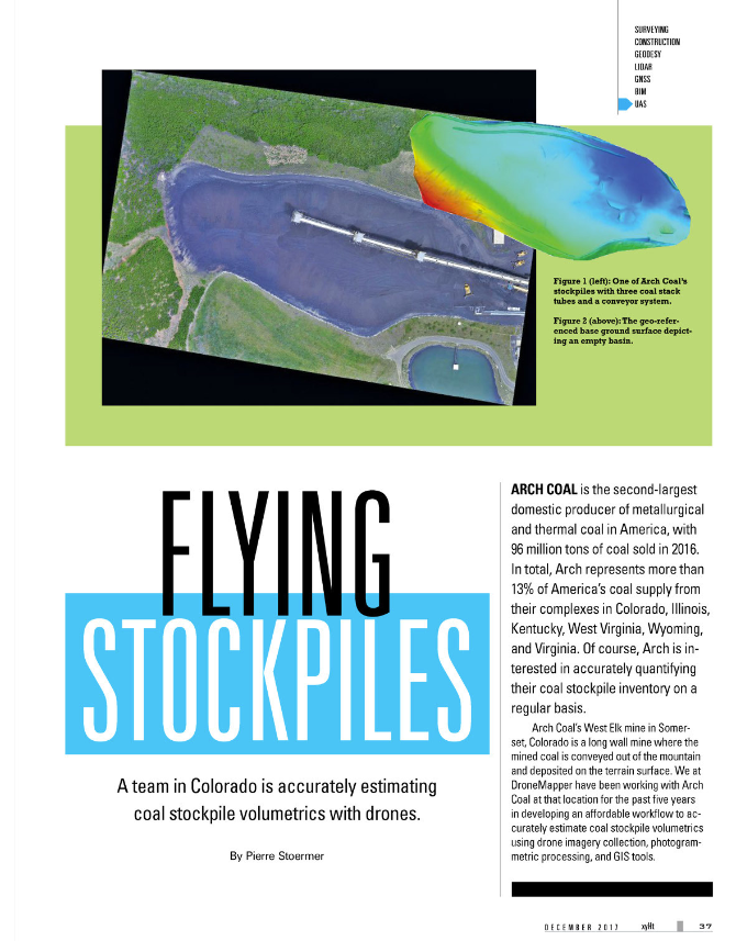
DroneMapper has been working with Arch Coal over the past 5 years in the development of an affordable work flow to accurately estimate coal stock pile volumetrics at the West Elk mine utilizing drone imagery collection, photogrammetric processing and GIS tools. The resulting work flow could lead to a significant cost saving by establishing accurate volumetrics with low latency compared with traditional manned aircraft operations. Further, more frequent drone acquired volume estimates can be used to check calibration of the real-time conveyor weight scale measurements to assure consistent calibration of mechanical systems.
Arch Coal – is the second largest domestic producer of metallurgical and thermal coal, with 96 million tons of coal sold in 2016. Arch is a well-positioned American coal company with large, modern, low-cost mining complexes and high-quality reserves in strategic U.S. coal supply basins. In total, Arch represents over 13% of America’s coal supply from their complexes in Colorado, Illinois, Kentucky, West Virginia, Wyoming and Virginia.
DroneMapper – provides photogrammetric cloud processing, desk-top software and GIS services for clients around the world. The team offers end-to-end drone operation services for imagery collections and processing as well as training. Typical products produced include high accuracy geo-referenced DEMs, DTMs, orthomosaics, point clouds, precision agricultural NDVIs, terrain contours and volumetric estimates, among others.
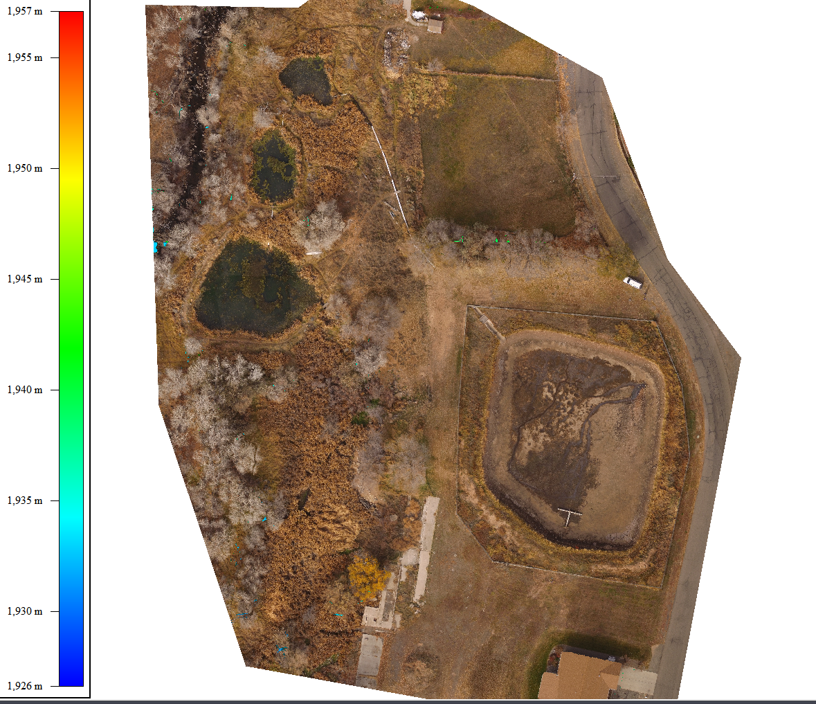
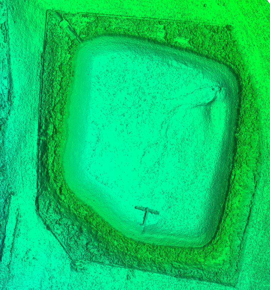
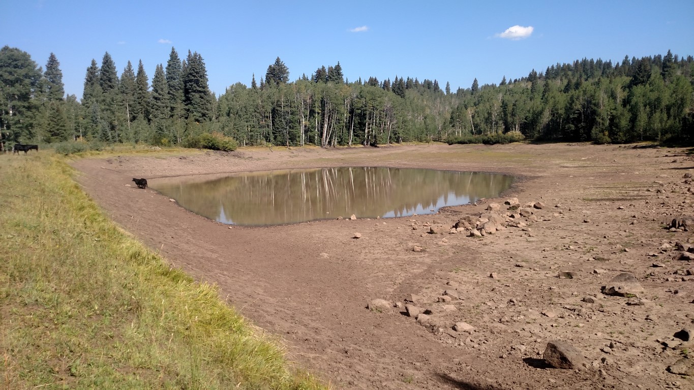
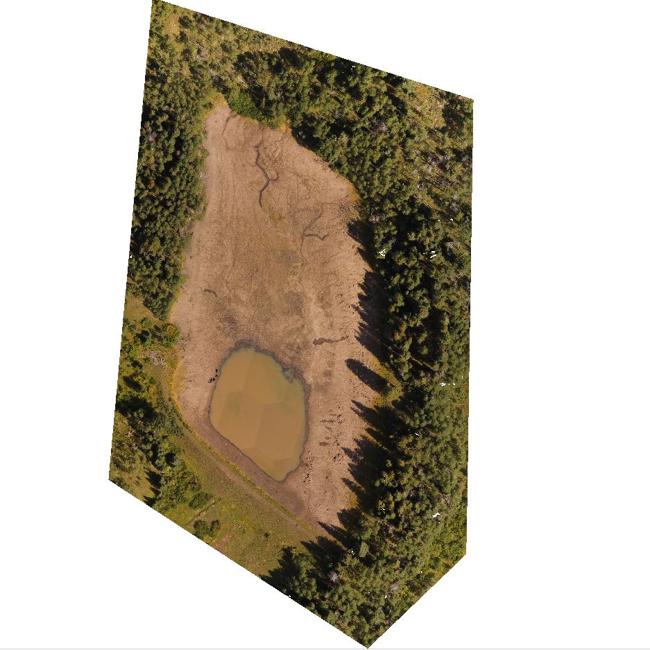
Arch Coal is interested in accurately quantifying their coal stockpile inventory on a regular basis. One example of this is the West Elk mine in Somerset, Colorado. The facility is a long wall mine where the mined coal is conveyed out of the mountain and deposited on the terrain surface. Figure 1 illustrates one of the stockpiles with three coal stack tubes (central left of image) with conveyor system. Ground control targets are used for every imagery collection to precisely align the imaged stockpile surface with the bare ground reference surface. Figure 2 shows the geo-referenced bare ground surface depicting zero volume or empty basin. This surface was precisely constructed using the control points that surround it. The colors represent the surface elevations with red the highest elevation and blue the lowest. Note the two ridges at the bottom of the surface illustration correspond to the ridge features seen in the stockpile image.
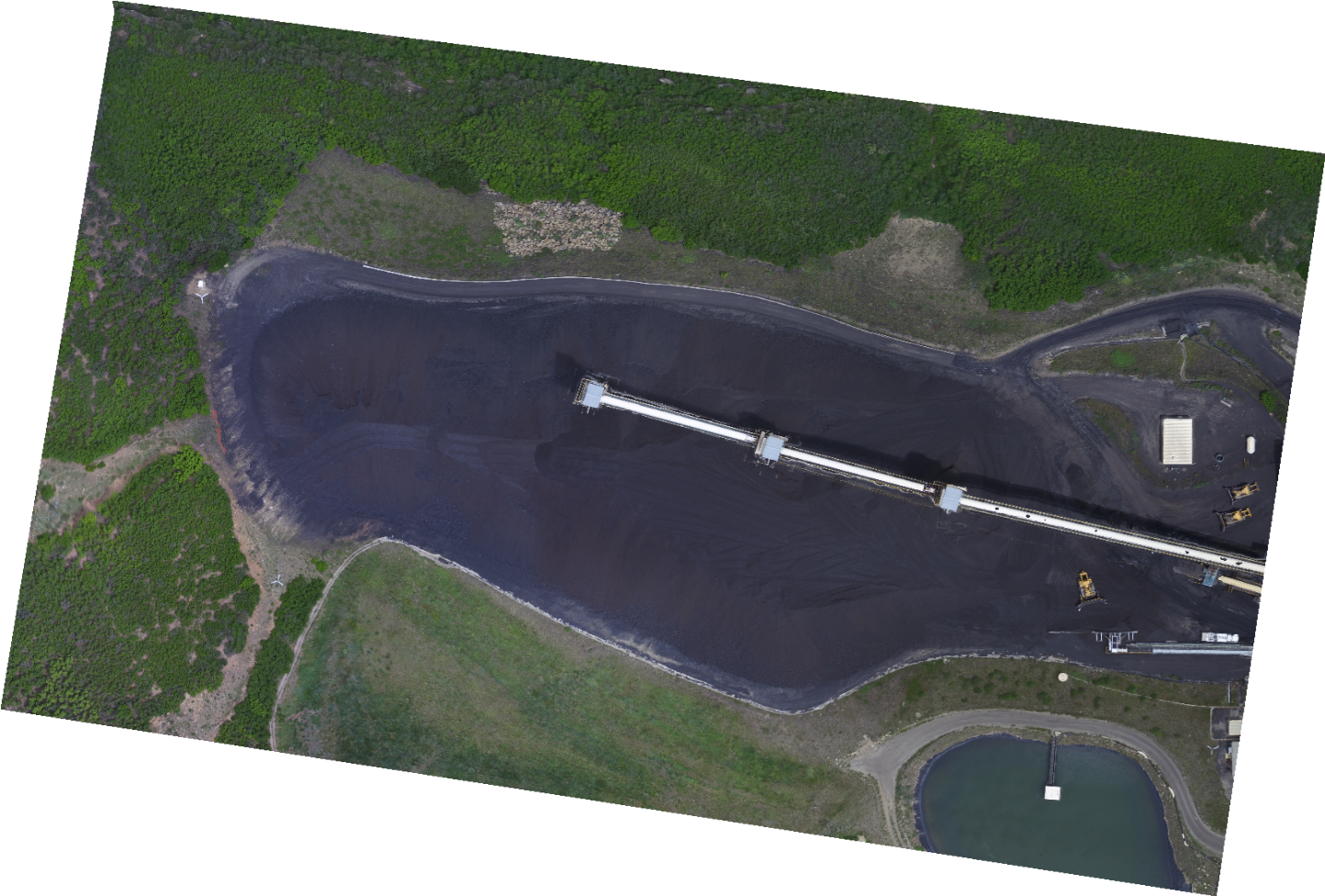
Figure 1: West Elk Stockpile
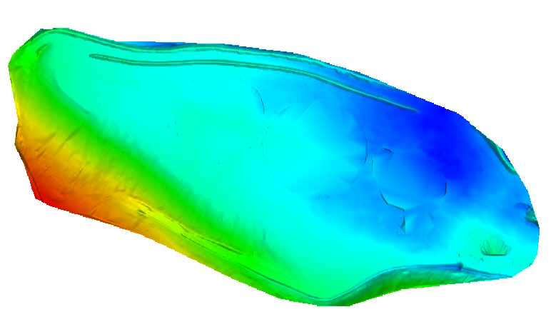
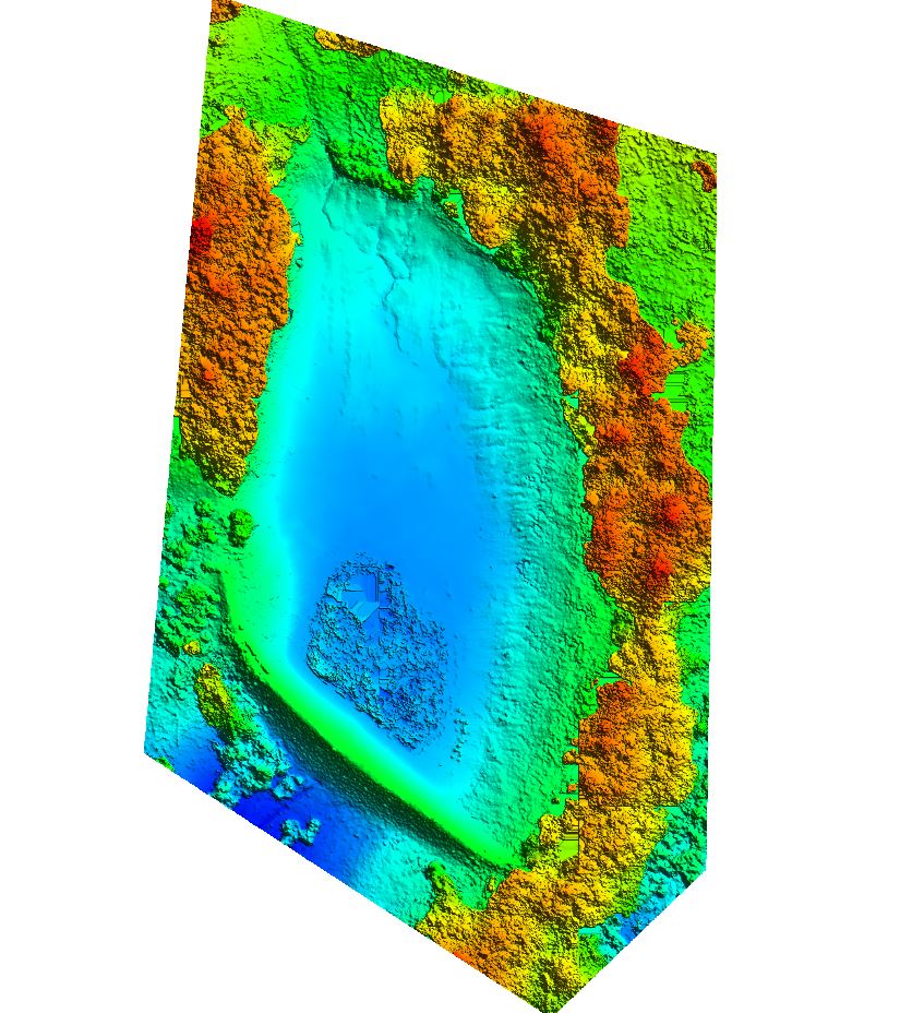
Figure 2: Geo-referenced Base Ground Surface
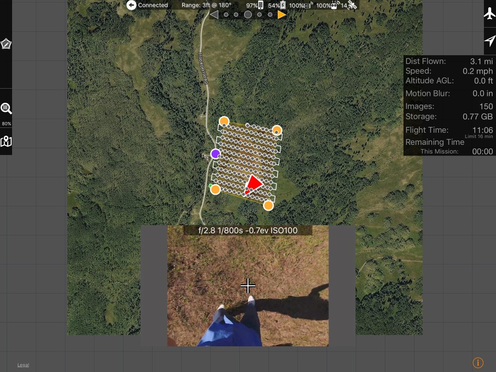
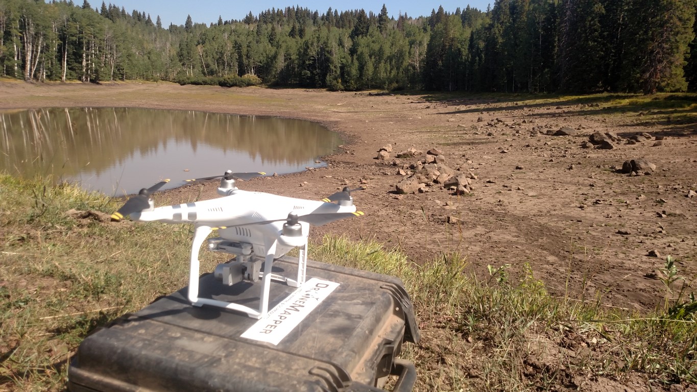
Imagery was collected by Arch Coal using a DJI Phantom 3 Advanced quad copter flying at approximately 300-400 feet above the ground/stockpile surface. At this elevation, the Phantom 3 will produce approximately a 2-inch pixel on the ground. A traditional 80% overlap (forward and side) grid was used for nadir imagery collection. The nadir imagery was augmented with an orbital oblique imagery collection to obtain stockpile surface data obscured by the conveyor system above the piles. Figure 3 illustrates the camera pose during the collection for both the nadir and oblique shots. DroneMapper has shown that the use of nadir and obliques provide for a higher quality digital elevation model (DEM) with less noise and artifacts than nadir alone. Once collection was completed the images were sent to DroneMapper for control pre-processing, full photogrammetric processing to generate the DEM and GIS manipulation for volumetric estimation.
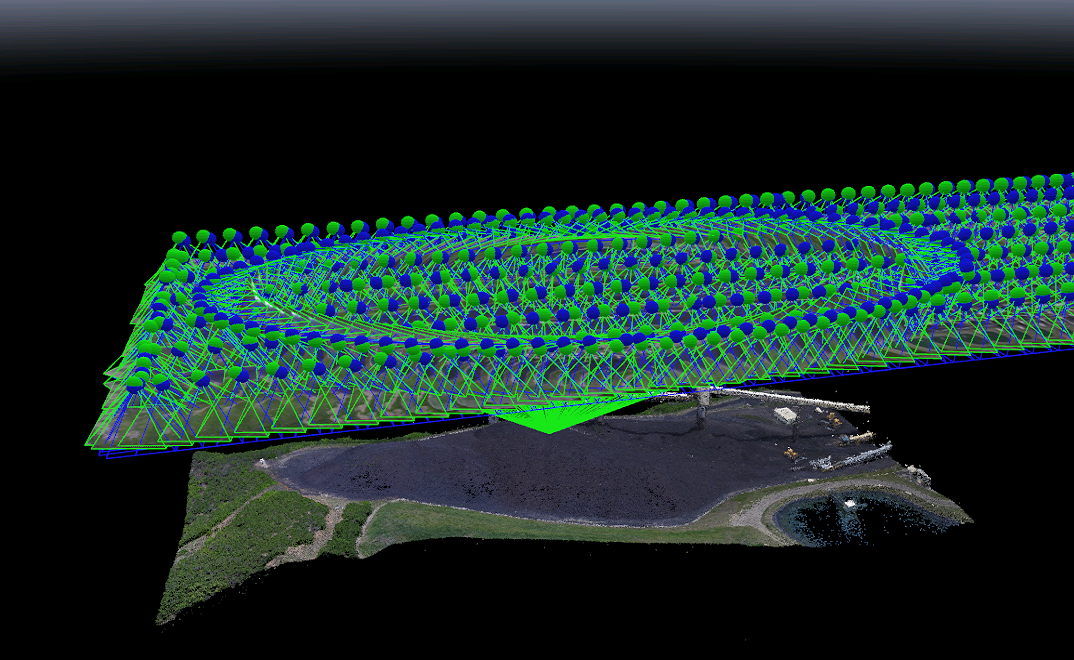
Figure 3: Nadir and Oblique Collection Utilization
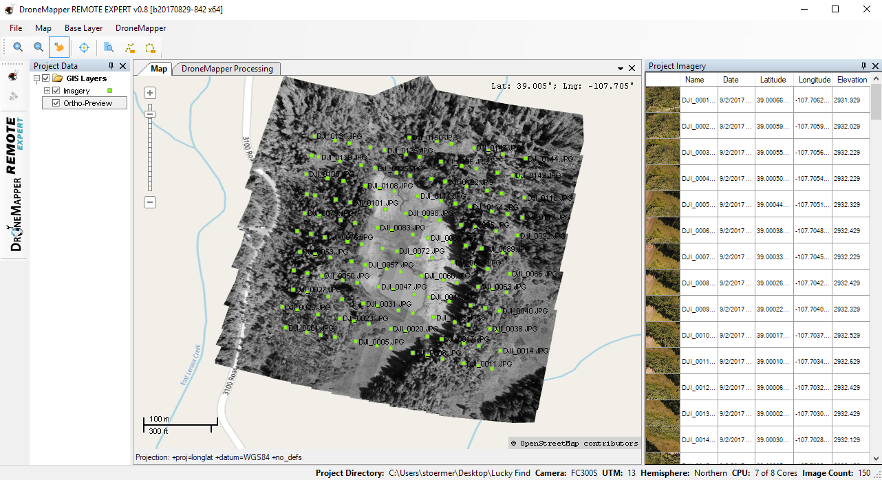
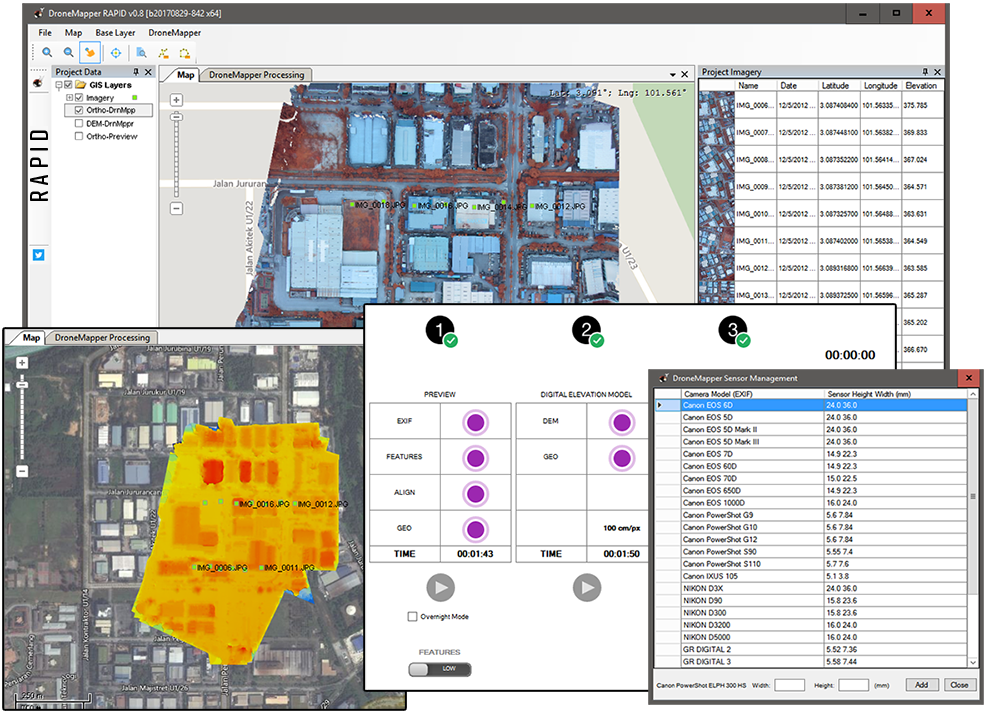
DroneMapper utilizes its Windows based REMOTE EXPERT software for 2-D control file generation and photogrammetry. The 2-D control file is generated using a tool that selects the number of images at a certain radial distance from the control by comparing the image geo-tags with the GPS coordinates of the control points. In this manner, an operator does not have to review every image for every control point in the scene, saving time. Each image identified with a control point is then zoomed in to select the pixel that the center of the control target appears. Figure 4 shows typical aerial target control points, 3-leg targets, used in image processing.
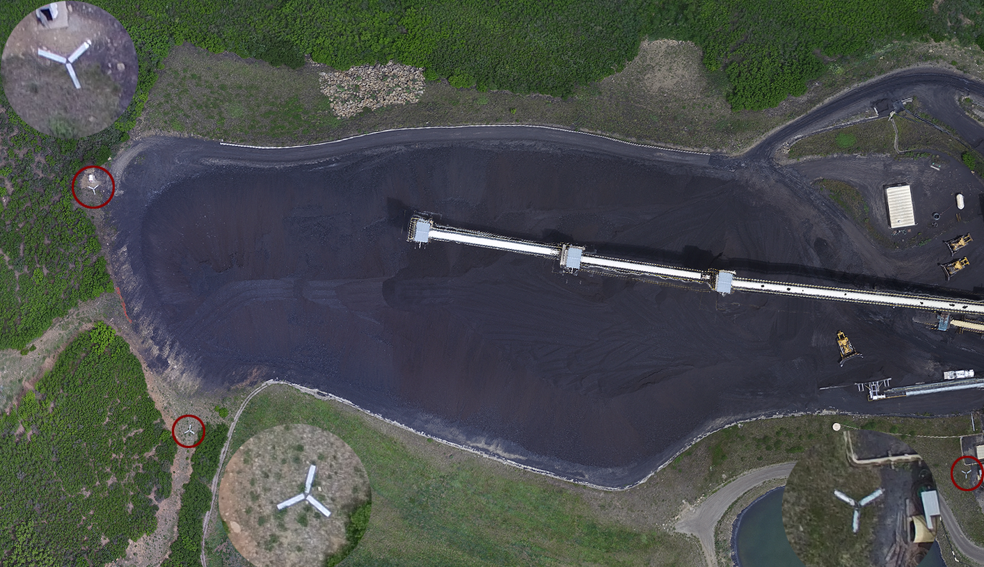
Figure 4: Mine Ground Control Points and Aerial Targets
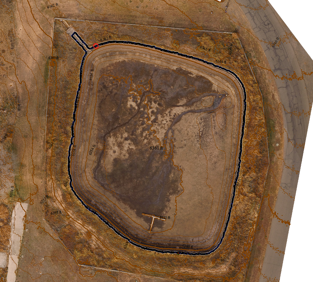
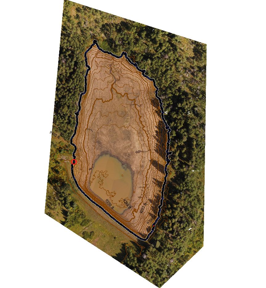
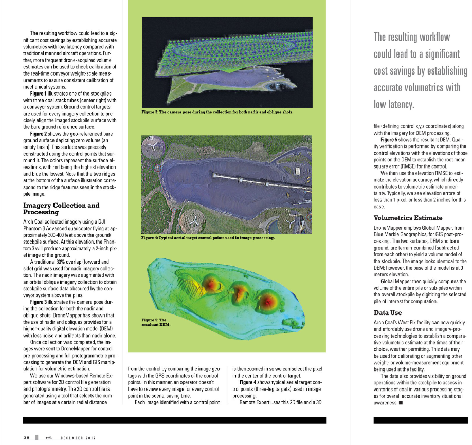
REMOTE EXPERT uses this 2-D file and a 3-D file (defining control X,Y,Z coordinates) along with the imagery for DEM processing. Figure 5 shows the resultant DEM. Quality verification is performed by comparing the control elevations with the elevations of those points on the DEM to establish the root mean square error (RMSE) for the control. The elevation RMSE is then used to estimate the elevation accuracy which directly contributes to volumetric estimate uncertainty. Typically, we see elevation errors of less than 1 pixel or < 2 inches for this case. 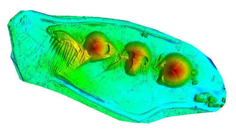
Figure 5: West Elk DEM
DroneMapper employs Global Mapper, from Blue Marble Geographics, for all GIS processing. The two surfaces, DEM and bare ground are terrain combined or subtracted from each other to yield a volume model of the stockpile. The image looks identical to the DEM above, however the base of the model is at 0 meters elevation. Global Mapper then quickly computes the volume of the entire pile or sub-piles within the overall stockpile by digitizing the selected pile of interest for computation.
Data Utilization:
Arch’s West Elk facility can now quickly and affordably utilize drone and imagery processing technologies to establish a comparative volumetric estimate at the times of their choice, weather permitting. This data may be used for calibrating or augmenting other weight or volume measurement equipment being used at the facility. The data also provides visibility on ground operations within the stockpile to assess inventories of coal in various processing stages for overall accurate inventory situational awareness.
Thank you, The DroneMapper Team