| ♥ 0 | Processing Oblique or Oblique + NADIR Imagery in 3D Mode
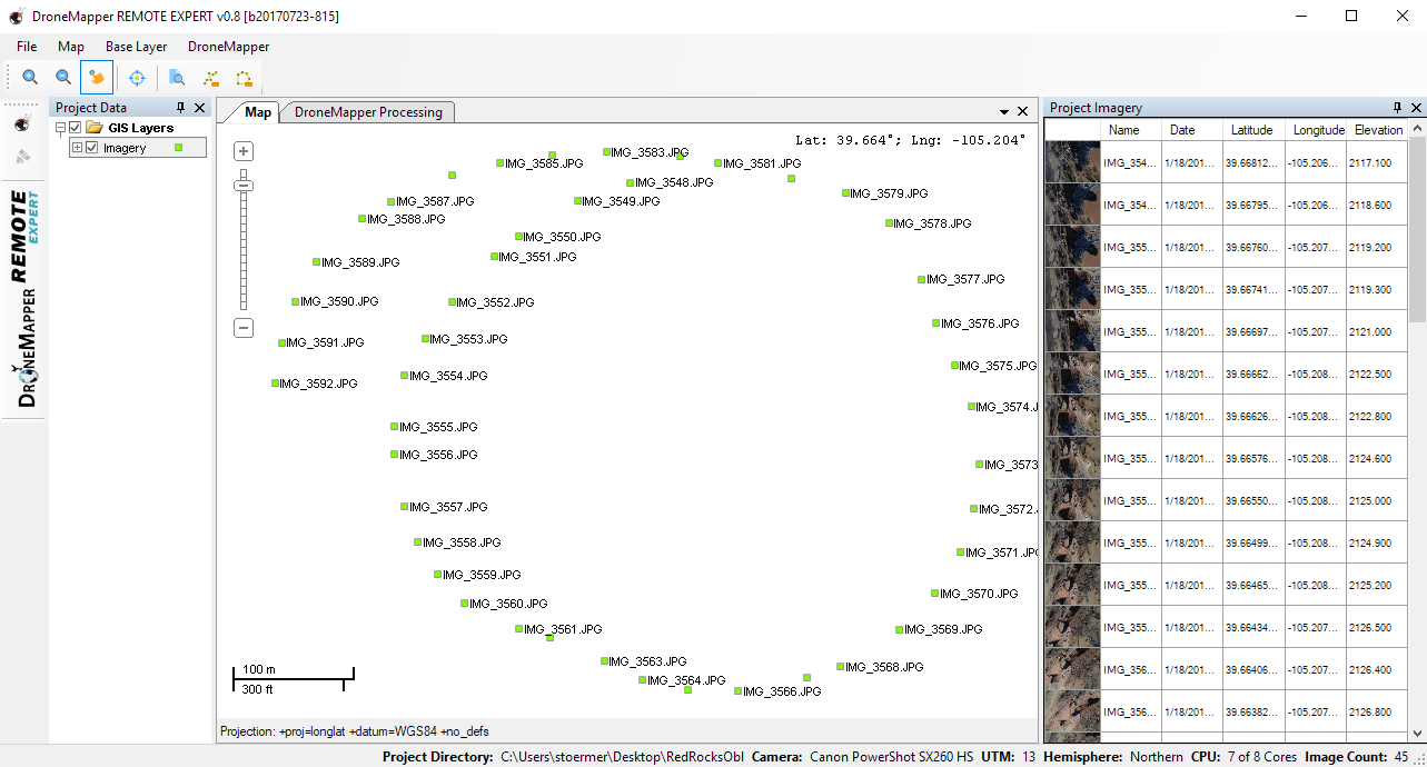
For this example we use the DroneMapper Red Rocks oblique imagery example located here: https://s3.amazonaws.com/DroneMapper_US/example/DroneMapper-RedRocks-Oblique.zip Processed results are located here: https://s3.amazonaws.com/DroneMapper_US/example/DrnMppr3D-RedRocks-Oblique.zip 1] Load the Red Rocks oblique data set in Drone Mapper REMOTE EXPERT (3D processing is not available in the free RAPID) We recommend creating a new folder on your Desktop and copying the example imagery here for processing. Do not process imagery on network drives, external hard disks or USB.
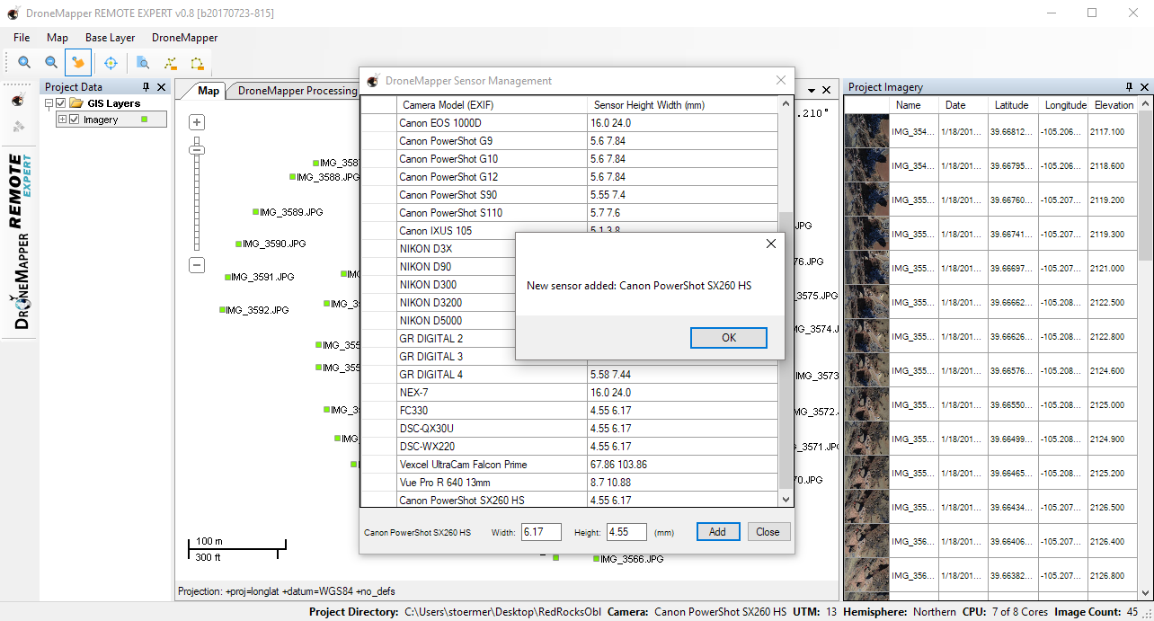
2] This imagery was collected in early 2012 using a Canon SX260HS, you will need to add this camera/sensor to your local camera database before processing. The CCD sensor size in mm is 6.17 (width) x 4.55 (height)
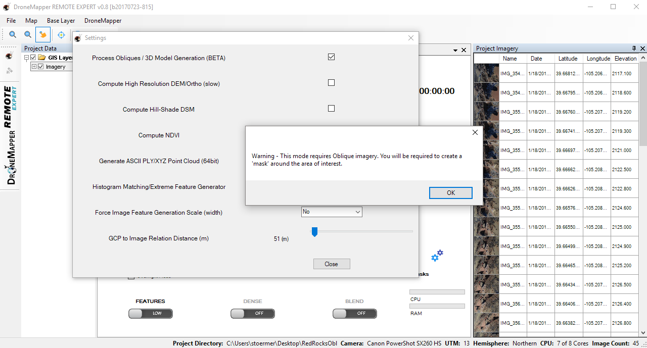
3] Enable 3D Model generation in the application settings. NOTE: This option should only be used when processing oblique imagery and/or oblique imagery + NADIR imagery. You will run into issues and possible application errors if you try and process oblique imagery and don’t enable this setting.
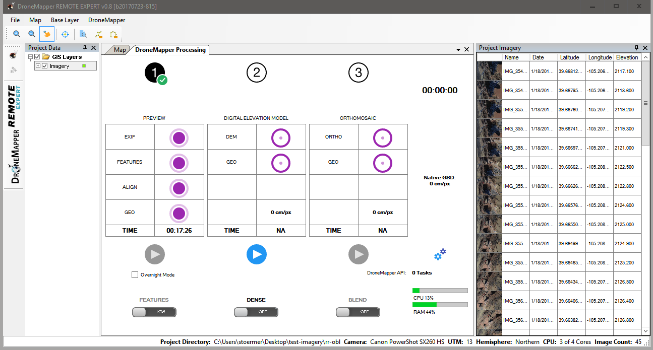
4] Press the “PLAY” button for the PREVIEW step and allow processing to complete. Once processing is completed, you will be present with a new dialog box where you will select the “Mask”. The “Mask” is the area of interest that you would like processed in high detail.
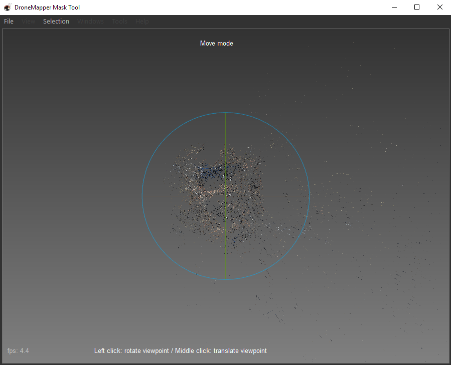
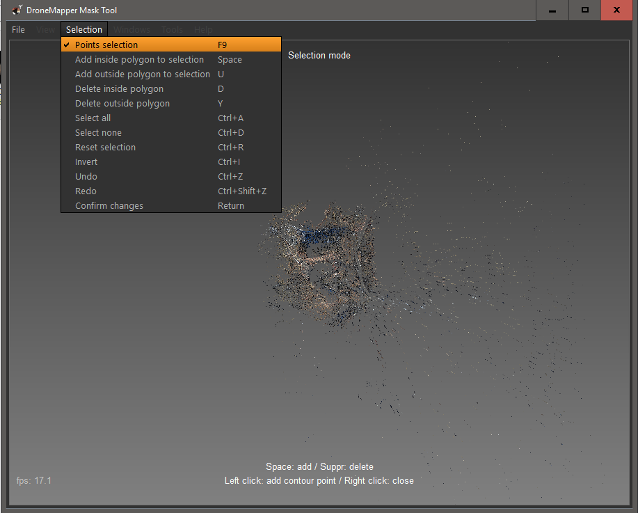
5] When the “Mask” tool is loaded, it initially starts in “Move mode” which will allow you to center the sparse point cloud into the center of the tool. NOTE: If you double click the center of the sparse point cloud it will automatically center. You can zoom in and out using the mouse scroll wheel. 6] The next step is to actually select the “Mask”, to do this you need to enter the “Points Selection” mode. Go to the “Selection” menu and choose “Points Selection” or hit F9.
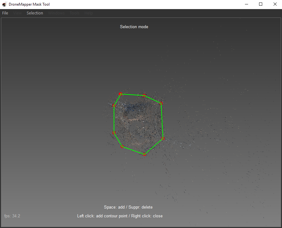
7] Create the “Mask” around your area of interest. Use the left mouse button to add polygon vertices. Connect all polygon vertices and click the right mouse button to stop adding points.
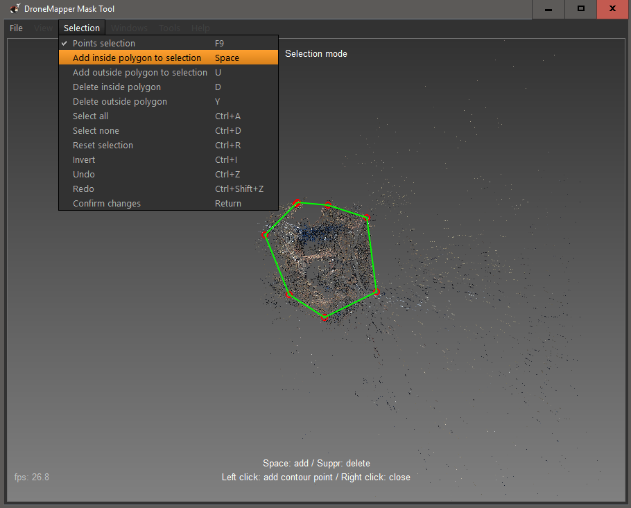
8] Go to the “Selection” menu and choose “Add inside polygon to selection” or hit the “Space” bar. This will create the selection mask. NOTE: You want to create your polygon over the area in the sparse point cloud where there is good data. You are filtering the outliers and points that are not part of the main area of interest using this method.
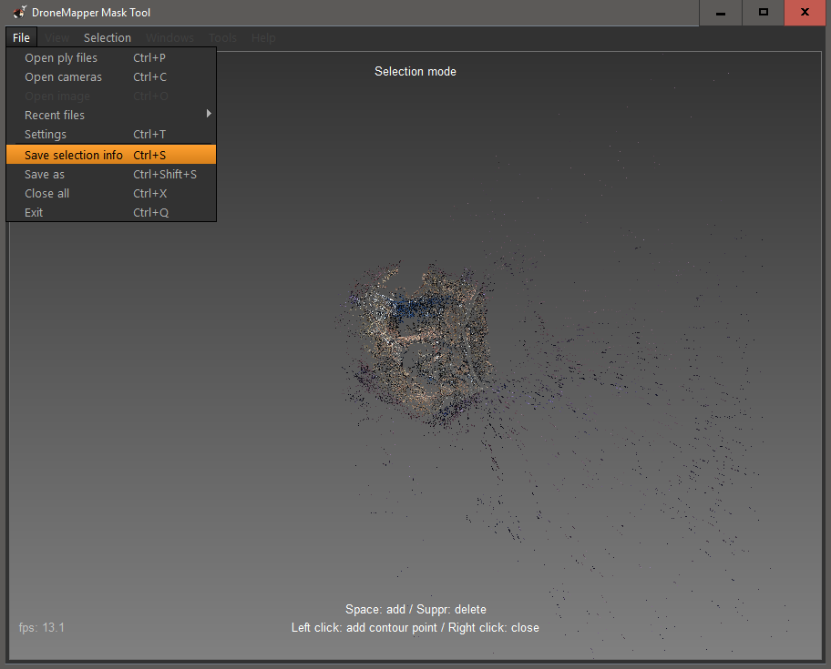
9] Go to the “File” menu and choose “Save selection info” or hit CTRL-S. This will save your selection into the current processing directory and allow processing to proceed.
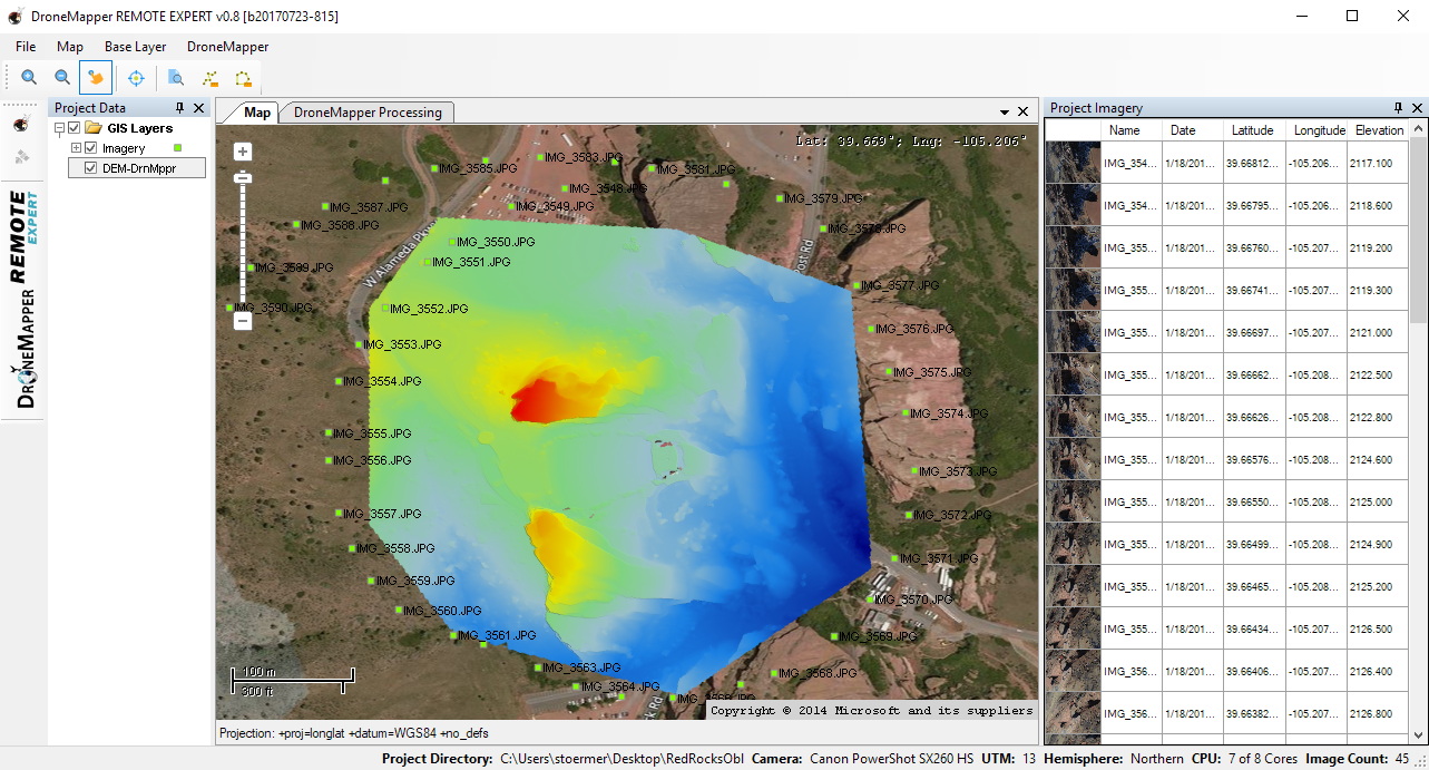
10] Go to the “File” menu and choose “Exit” or hit CTRL-Q. You are now ready to build the 3D Model and Digital Elevation Model. 11] Press the “PLAY” button for the Digital Elevation Model step. You can use the “DENSE” toggle switch to enable higher resolution 3D model processing if required.
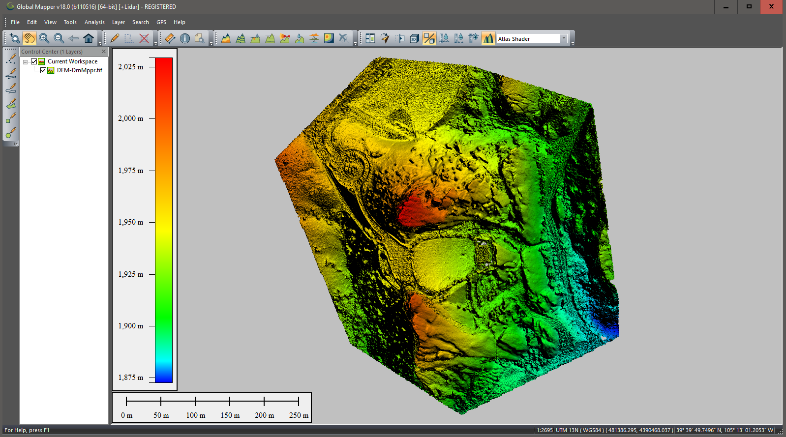
Results can also be verified and/or viewed using a tool such as Global Mapper:
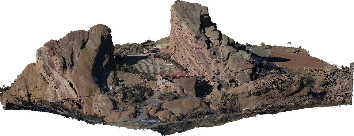
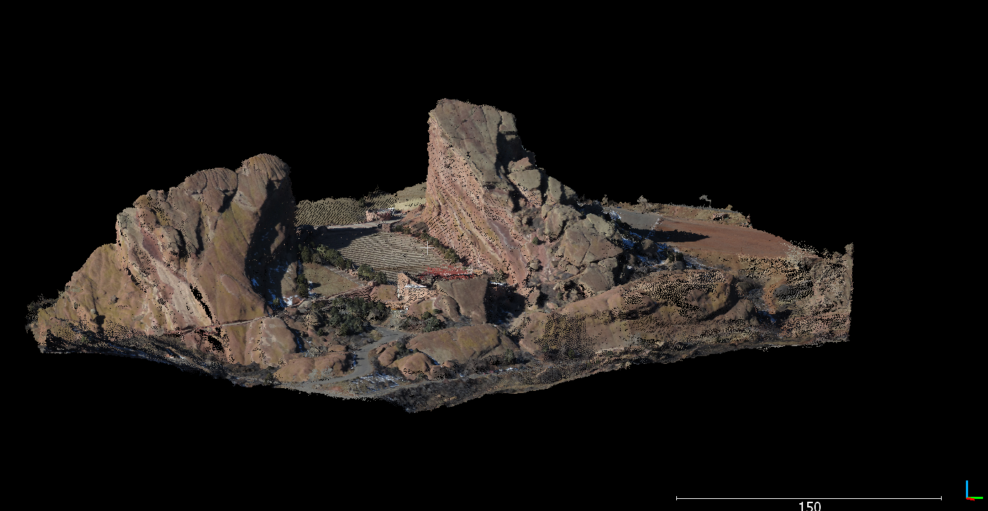
13] Press the “PLAY” button under the Orthomosaic step. This will generate a point cloud and a textured mesh. These point cloud and mesh files can be viewed in CloudCompare. You will be directed back to the “Map” view but the application will not add a new layer to the map. We currently don’t have a way to visualize 3D point clouds or mesh inside the DroneMapper desktop suite. 14] View point cloud results in CloudCompare:
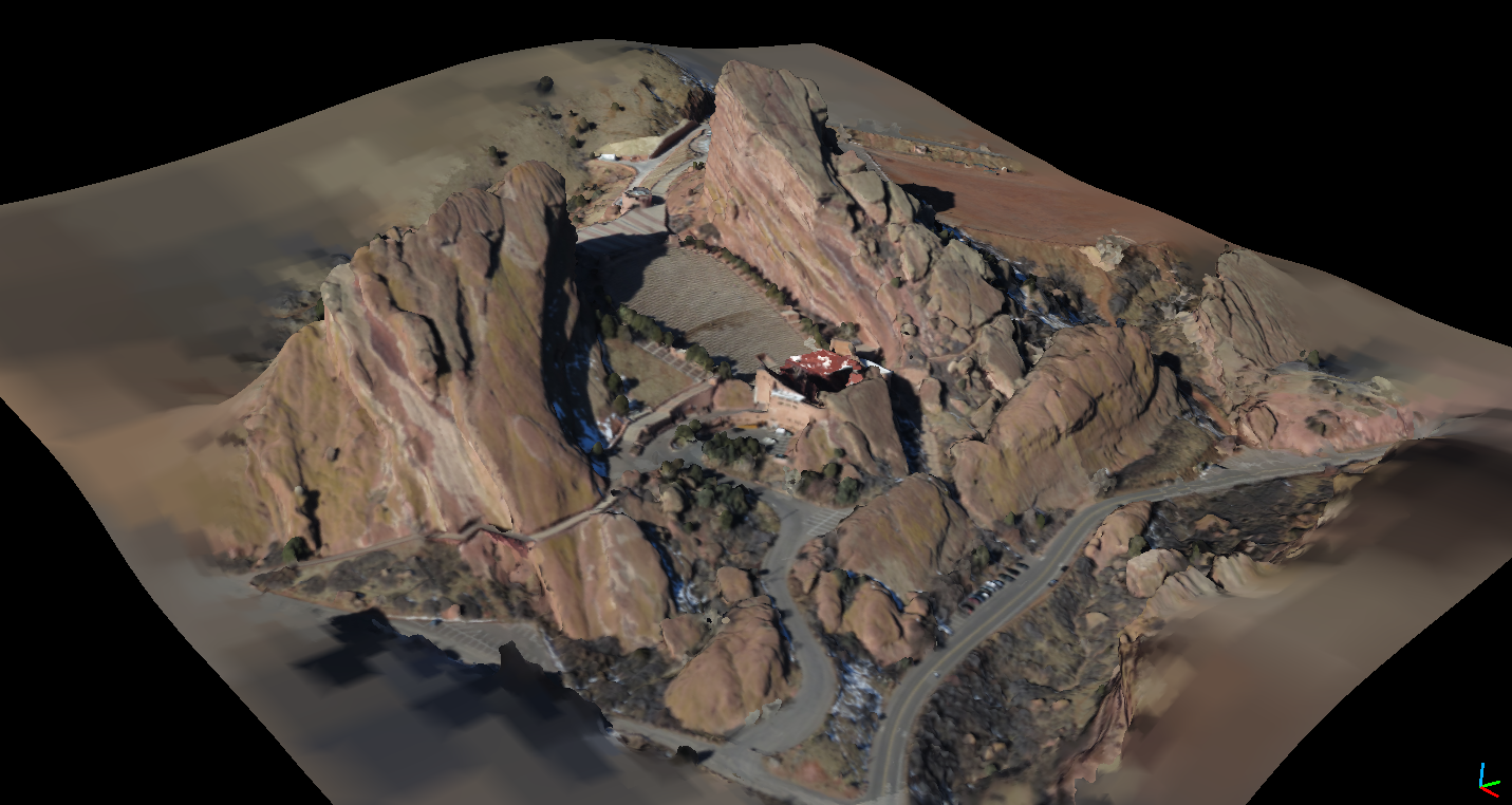
15] View point cloud textured mesh in CloudCompare:
NOTE: Textured mesh creation is in the early stages of development and will improve as time permits. Thanks Marked as spam |