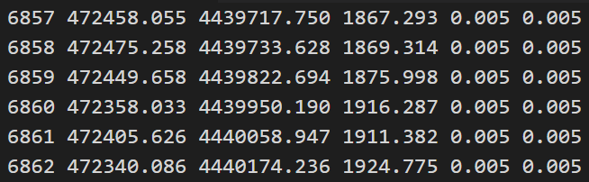
| ♥ 0 | Ground Control Point (GCP) 2-D File Generation For drone mapping applications that require absolute geo-spatial accuracy REMOTE EXPERT provides full processing with the use of GCPs. There are two additional files required along with the project imagery to make full use of this important function. The first file is the DroneMapperGCP_3D text file. An example file is shown below:
This text file contains 6 columns of data, each row spaced delimited. Let’s look at the first row: the first entry is the GCP name (6857), followed by a space. The second entry is the easting coordinate in UTM (zone) WGS84, meters (472458.055), followed by a space. The third entry is the northing coordinate in UTM WGS84 (4439717.750), followed by a space. The fourth entry is the elevation in meters (1867.293), followed by a space. The fifth (horizontal) and sixth (vertical) entries are the survey precision (0.005), separated by a space. This point was surveyed with an accuracy of 5 mm. Each GCP to be used in processing is listed in the remaining rows. Once completed, save this file as DroneMapperGCP_3D.txt within the project imagery folder.
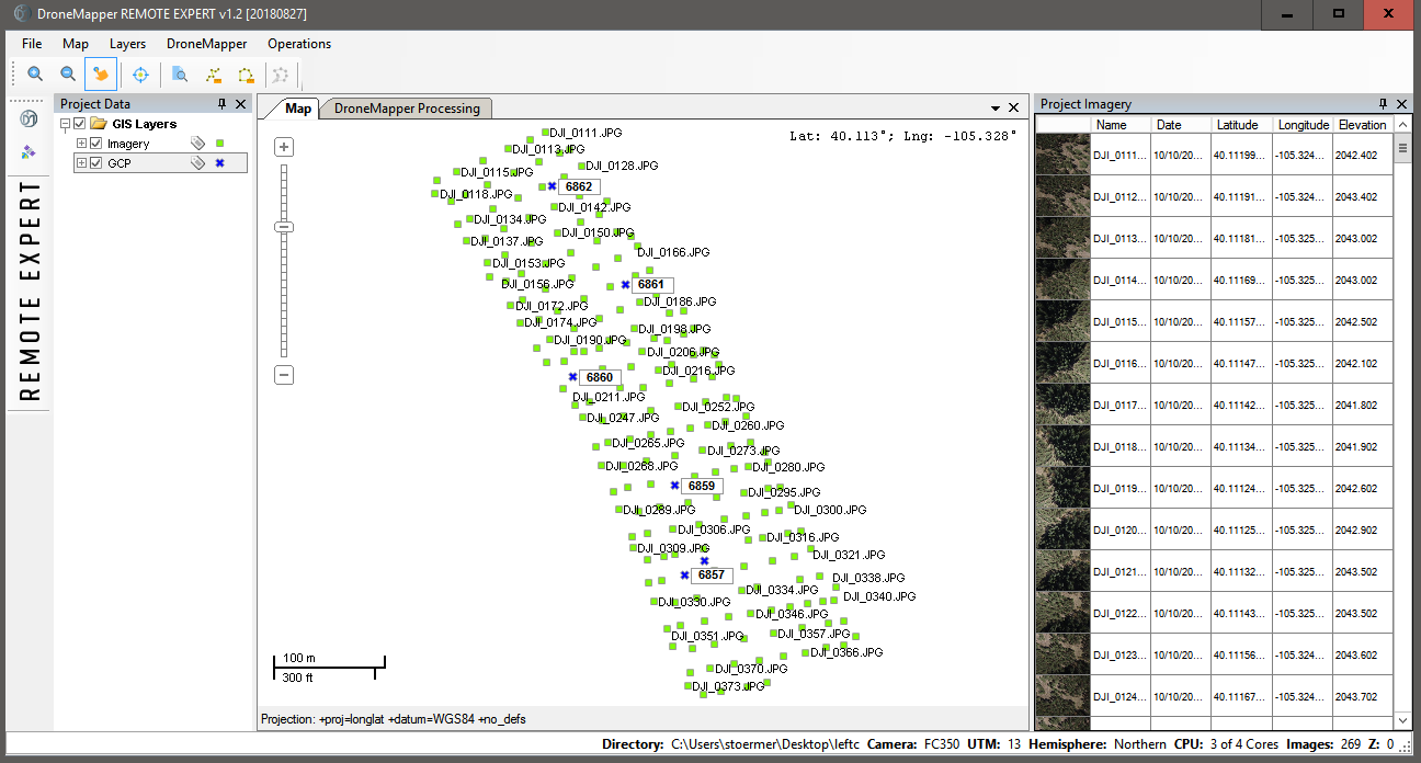
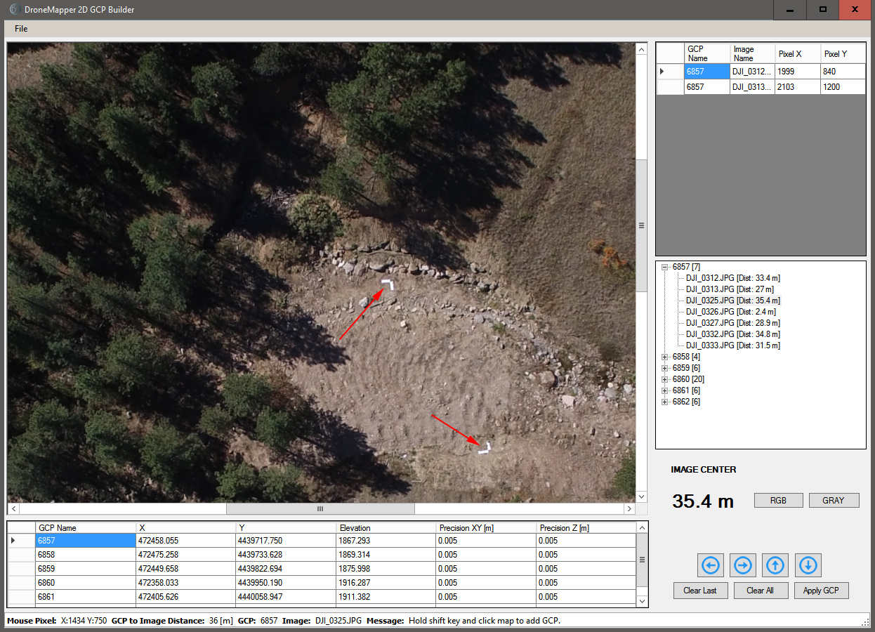
When the application is opened and JPGs are loaded the user will see the following window after clicking on the GCP tool beneath the DroneMapper go icon:
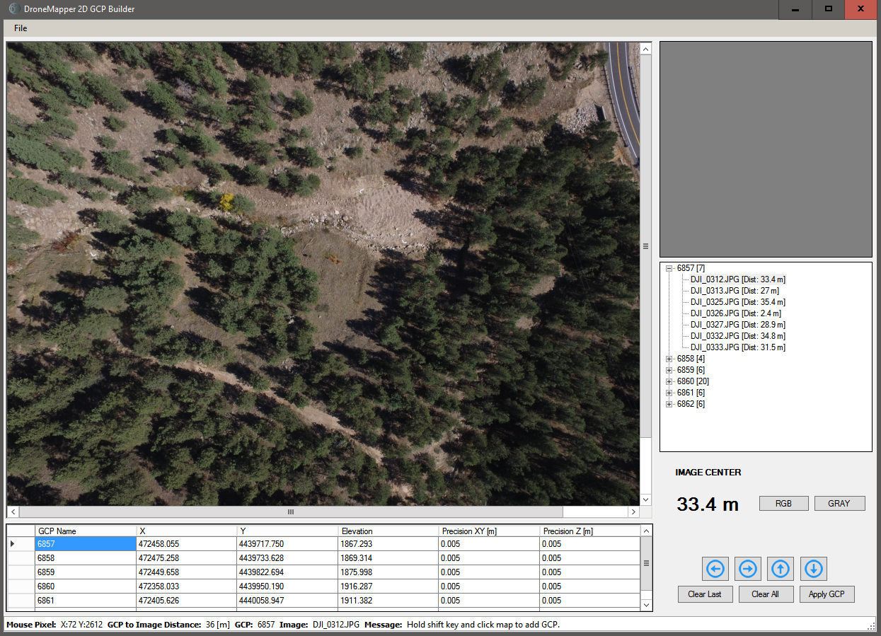
An associated image (for GCP 6857) is illustrated with all GCPs listed below and all images associated with the GCPs tabulated to the right. The user zooms in on the image and places the pointer on the GCP surveyed position, presses shift and clicks the mouse button for selection as shown in the next screenshot:
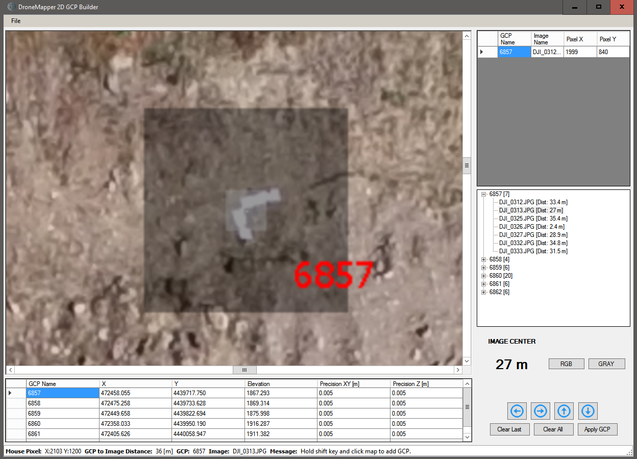
The inside corner of the “L” was selected as the surveyed point. At the top right hand corner of the screenshot the pixel selected in that image is recorded. After selection of the pixel the next image in series for that GCP is displayed. The same process is repeated until all images for that GCP have had pixels identified. The blue down arrow is pressed to move onto the next GCP and the process repeated until all images are associated with GCPs and image pixels have been selected. Once completed click on the “Apply GCP” icon and the DroneMapperGCP_2D text file will be written to the project image folder. Tips, Suggestions and Cautions Here are a few tips/suggestions/cautions to help quickly generate the GCP 2D file without errors. One error in the file generation will cause processing to abort.
Marked as spam |