DroneMapper REMOTE: Accurate, Affordable and Accelerated Processing for UAS Remote Pilots

JP Uncategorized

Accurate, Affordable and Accelerated Processing for UAS Remote Pilots
Introducing DroneMapper REMOTE

Pierre Stoermer, CEO – DroneMapper.com


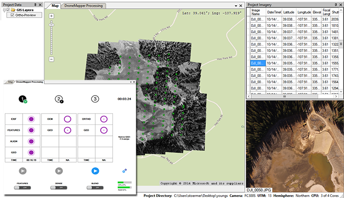
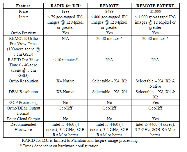
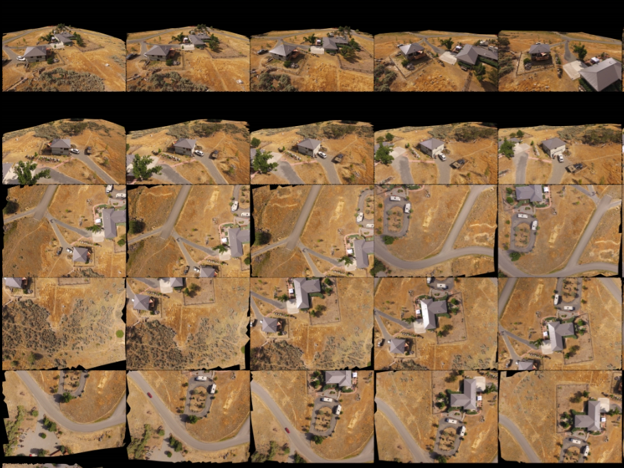
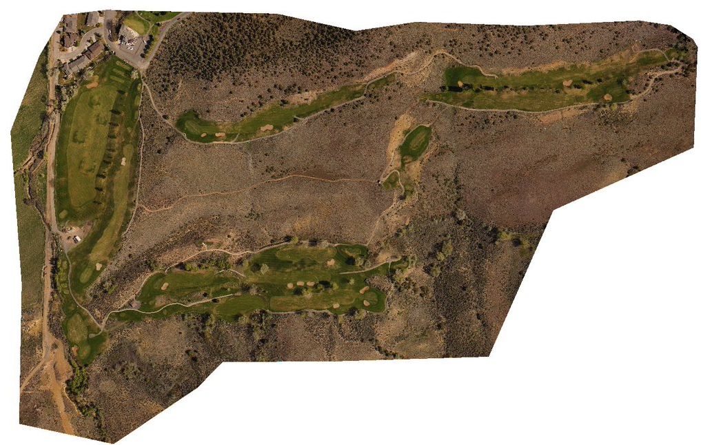
In 2017, DroneMapper will be offering its photogrammetry software to the UAS mapping marketplace, as a Windows application. REMOTE will provide geo-referenced orthomosaics and digital elevation models (DEMs) in the field on your laptop in near real time. Without packing up your UAS mapping platform, simply load your imagery into the application and generate a preview orthomosaic to confirm all went well with the collection. At the site or back at the office you can choose to finish processing at scaled resolutions for quick turnaround or at higher resolutions (REMOTE EXPERT) depending on your client’s needs. A free version, RAPID for DJI will also be offered to allow Remote Pilots operating DJI Phantoms or Inspires to evaluate the software for smaller areas of interest. Features of all offered versions are shown in the table below:

Times shown in table are for the Intel i5-4460, 3.2 GHz (4 cores), 8 GB RAM with 3 of the 4 cores utilized for processing. Your times will be dependent on what laptop hardware you bring to the field.

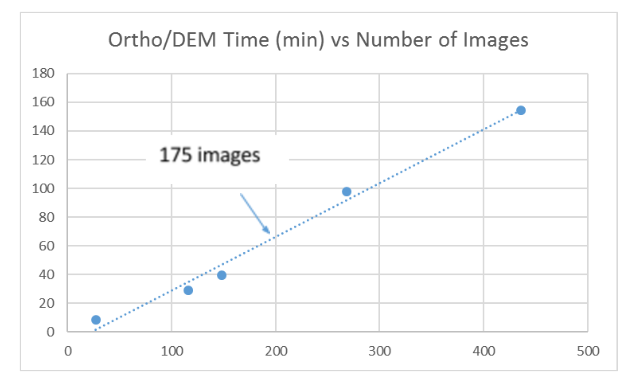
The chart below illustrates the total time for scaled ortho and DEM production in the application vs the number of images loaded using the hardware described. This is the time to produce an ortho at X4 native and the DEM at X8 native resolutions.

For the 100-acre scene the scaled DEM and ortho will render in about an hour, inclusive of the preview ortho time. For RAPID’s 40-acre scene scaled products are generated within 20 minutes.

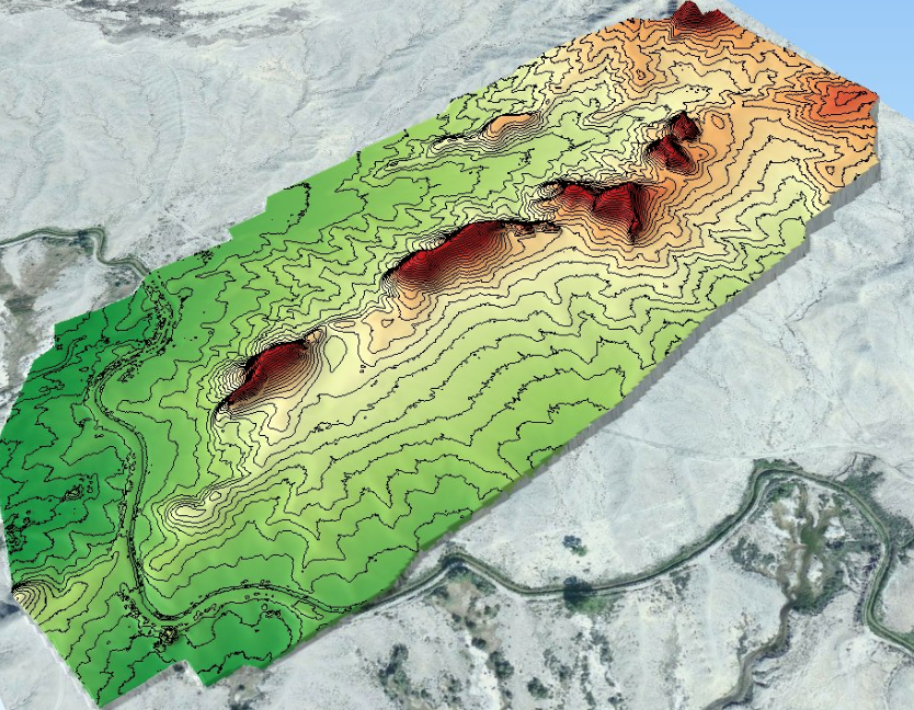
REMOTE provides very quick feedback on the quality of the collection using the data Preview function and accurate scaled output products that are usable for applications requiring topography, contours and volumetric estimates.

REMOTE EXPERT adds additional functionality in output product scale selectability, use of ground control for absolute mapping accuracy and the ability to map much larger areas.

Please contact us for additional information on our RAPID and REMOTE software products.

The DroneMapper Team


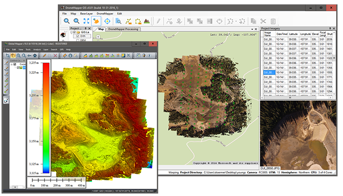
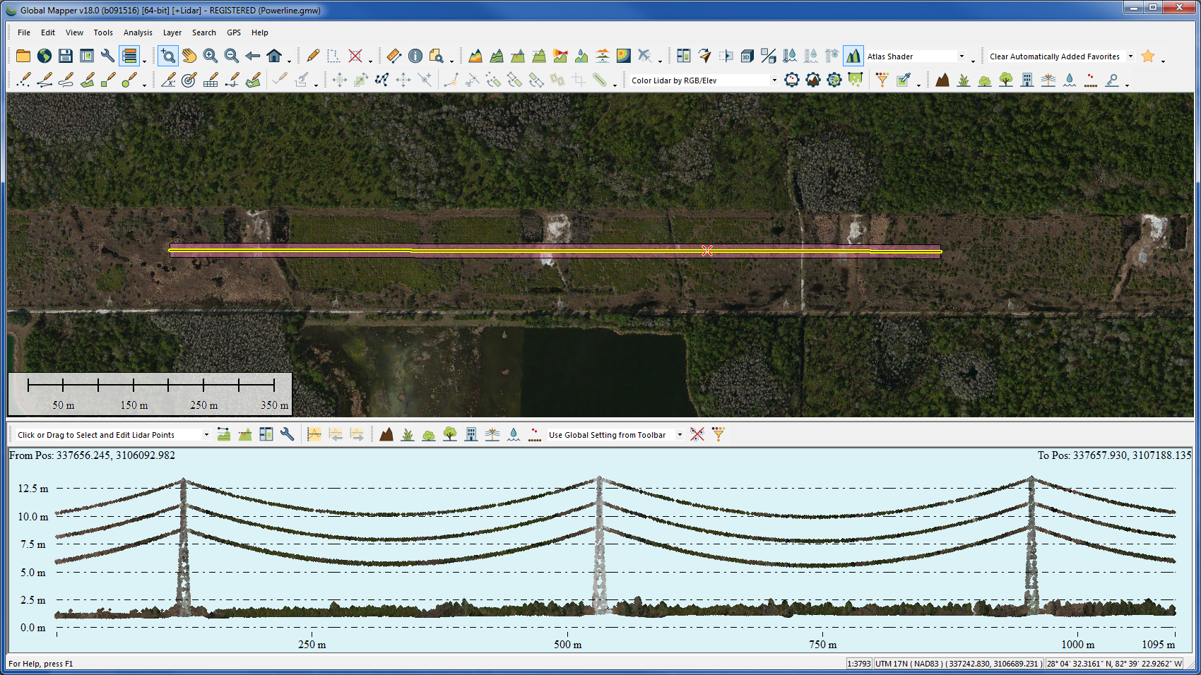
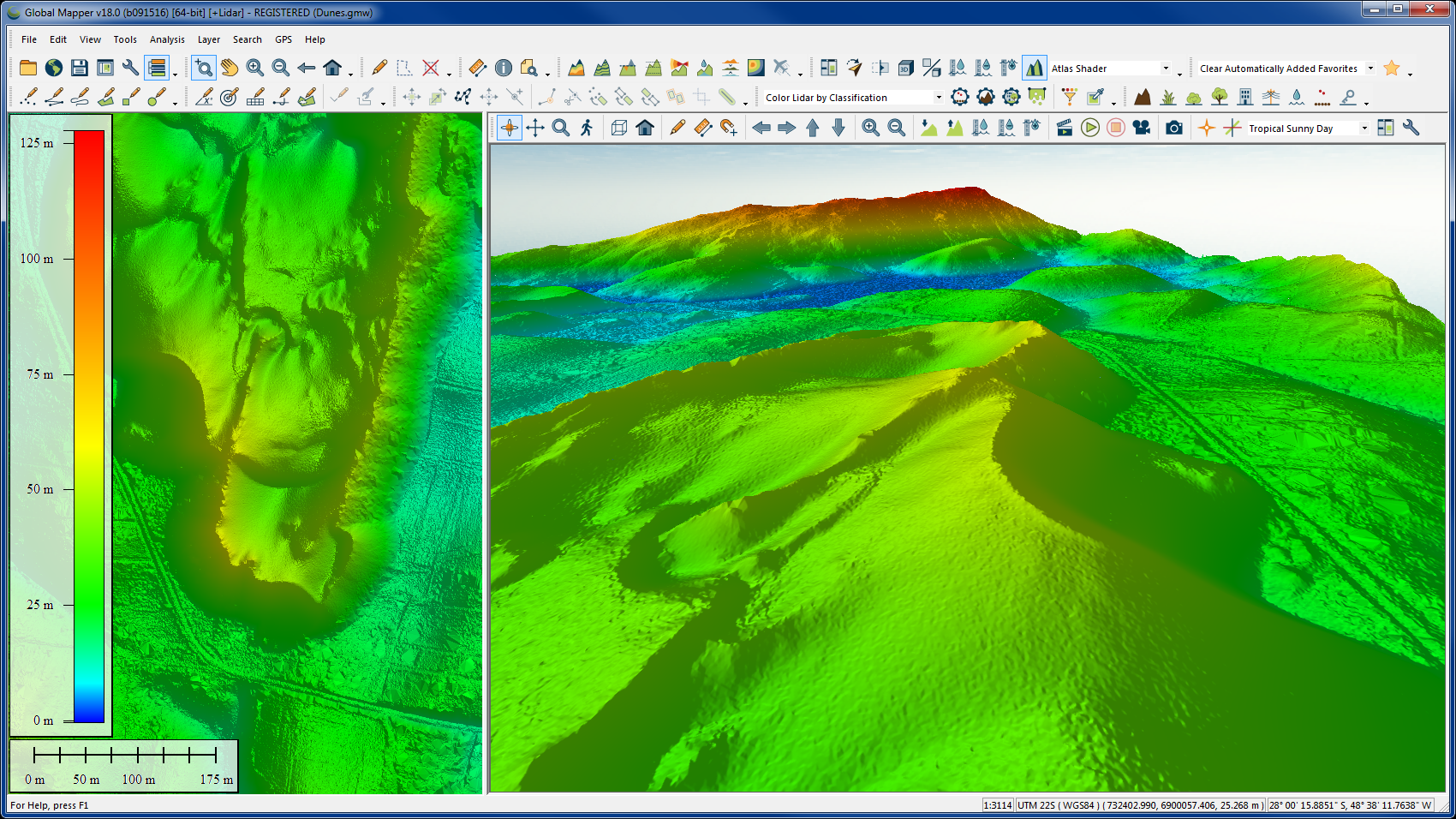
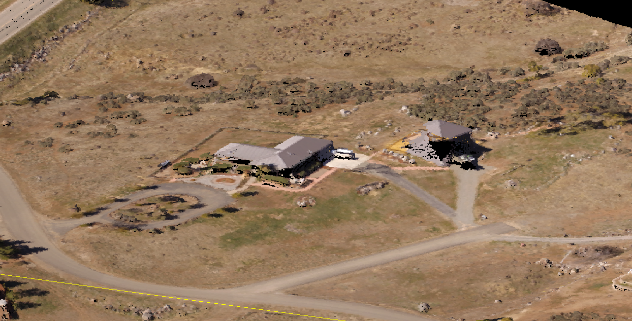
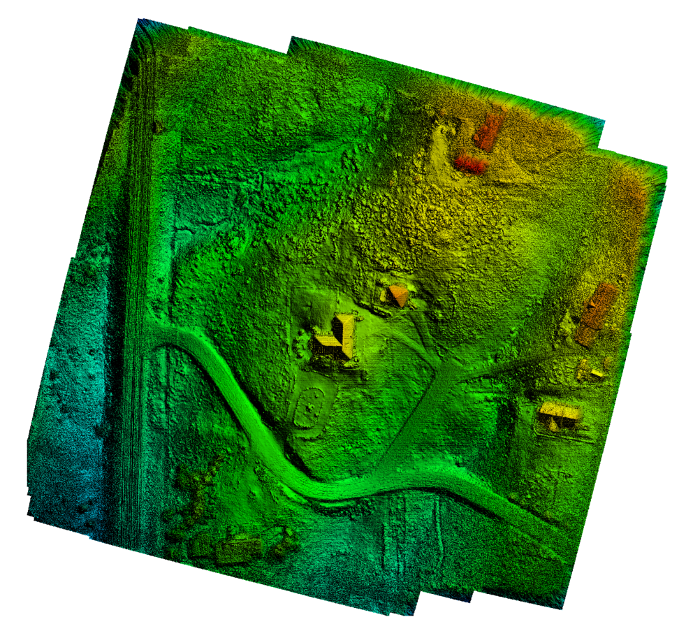
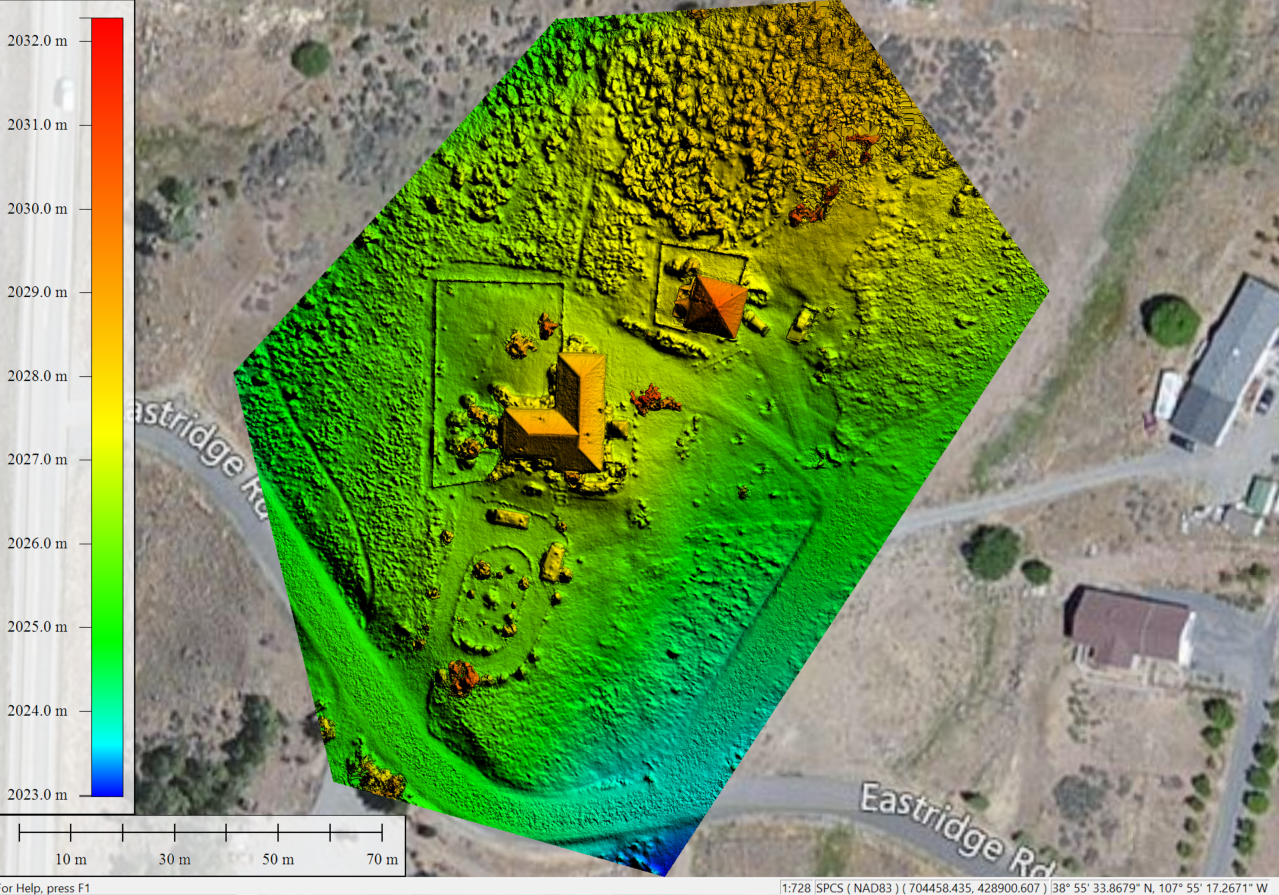
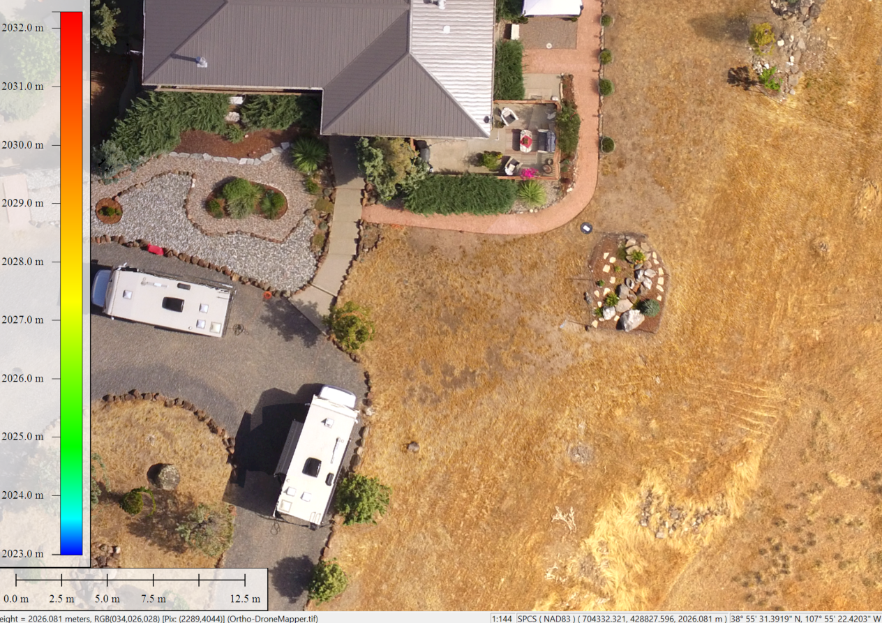
*DroneMapper REMOTE DEM product viewed with Global Mapper v18


Approved Reseller of Global Mapper

JP Uncategorized

DroneMapper: Approved Reseller of Global Mapper
Pierre Stoermer, CEO – DroneMapper.com


As many of you know we have been recommending Blue Marble Geographics’ Global Mapper as the go to GIS software package. Global Mapper provides effortless rendering of our orthomosaics and digital elevation models, a vast and powerful tool set for value added product generation, intuitive and affordable and extensive support to users. We are very pleased to announce that we have been approved as a limited reseller of Global Mapper Software.


For you, Part 107 remote pilots and 333 exemptees, involved in the surveying, construction, mining, precision agricultural industries, to name a few, this is must have software! Visualize your maps in both 2-D and 3-D, make precision measurements and generate CAD software compatible outputs in a snap.

Overview and details of Global Mapper software capabilities can be found here:
http://www.bluemarblegeo.com/products/global-mapper.php

Licensing and purchasing information for Global Mapper software can be found here:
http://www.bluemarblegeo.com/products/global-mapper-purchase.php

Please contact us to discuss your specific needs and how Global Mapper can improve the efficiency and quality of your workflows.

“Mind the gap between world and map”

Geospatial Accuracy and Optimal DEM Construction Utilizing Nadir & Obliques

JP Uncategorized

DroneMapper Labs: Geo-spatial Accuracy and Optimal DEM Construction Utilizing Nadir & Obliques – 8/24/16
Pierre Stoermer, CEO – DroneMapper.com
 

This post addresses two topics 1) expected positional accuracy using ground control and 2) utilizing a combination of nadir and oblique images for optimal DEM construction.

Geo-spatial Accuracy:

Here we report on a set of recent imagery collections utilizing primarily UAV platforms (one manned platform included – Project L) with varied collection sensors. In each case well surveyed ground control was used in the processing of the DEM and orthomosaic. In each of the DEM/ortho sets the position of the control was compared to the surveyed coordinates to compute horizontal and vertical root mean square errors (RMSEs). All measurements were accomplished utilizing Global Mapper, version 16.2. The table below illustrates seven data sets with RMSEs computed.

Examples of DroneMapper Ortho & DM Ground Control Geo-spatial Errors (RMSE)

Project Scene Area (sq. Km) GCP Number Imagery GSD (cm) Camera Used Average Horizontal Error (RMSE – cm) Vertical Error (RMSE – cm)
L 180 27 14 UltraCam Falcon prime 2.85 7.9
B 1.15 22 3 Sony a5100 1.3 3.5
CB 0.56 7 4.7 DJI FC-300 3.2 3.6
WE 0.66 8 5.9 Sony NEX-5R 4.34 5.21
TB-1 0.56 5 5.6 DJI FC-350 2.3 3.3
TB-2 0.94 5 7.4 DJI-FC-350 3.6 4.66
McB 0.88 7 6.2 DJI FC-300X 2.2 5.2

The data sets include a manned aircraft using Vexcel’s UltraCam Falcon prime (Project L), two fixed wing UAVs using Sony cameras (Projects B and WE) and four DJI quad-copter UAVs using the FC series of sensors (Projects CB, TB-1, TB-2 and McB). In all cases except one, Project B – vertical error, the horizontal and vertical RMSEs are sub-pixel (compared to the native GSD).

When we average the four DJI project horizontal and vertical errors as a percentage of GSD we see that one could expect an error of one-half pixel horizontal and three-quarters pixel vertical. In terms of absolute map accuracy with 95% confidence one could expect 1.2 pixels horizontal and 1.5 pixels vertical. So for you DJI operators, if your application requires absolute vertical accuracy of 3”, plan on imaging at 2” pixel GSD or less with well surveyed control.

Nadir and Obliques for DEM Construction:

A set of nadir and oblique images were collected for a mining operation, interested in accurate volumetric estimation. The accuracy of the estimate is dependent on the pile size and vertical error. We used a DJI Phantom 3 flying at an AGL of approximately 200’ (GSD: ~ 1”). Four (4) existing ground control points (GCP) were utilized for precise geo-referencing of the ortho and DEM. An example GCP from the ortho along with the ground truth position (black labeled dot) is illustrated in Figure 1.
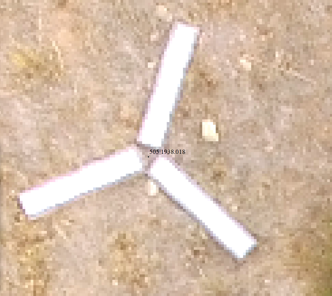

Figure 1: Typical Ground Control Point

In this case, GCPs are used for referencing the stockpile surface to a bare ground DTM in order to accurately measure temporal changes. The mining operation utilizes an above pile conveyor system for stockpile distribution. For traditional nadir only image collections the conveyor obscures the pile surface, making accurate surface definition below it difficult. We utilized both nadir and oblique images in order to see the pile surface that is typically obscured with nadir only images. Figure 2 shows a point cloud of one of the stockpiles along with the conveyor structures overhead.
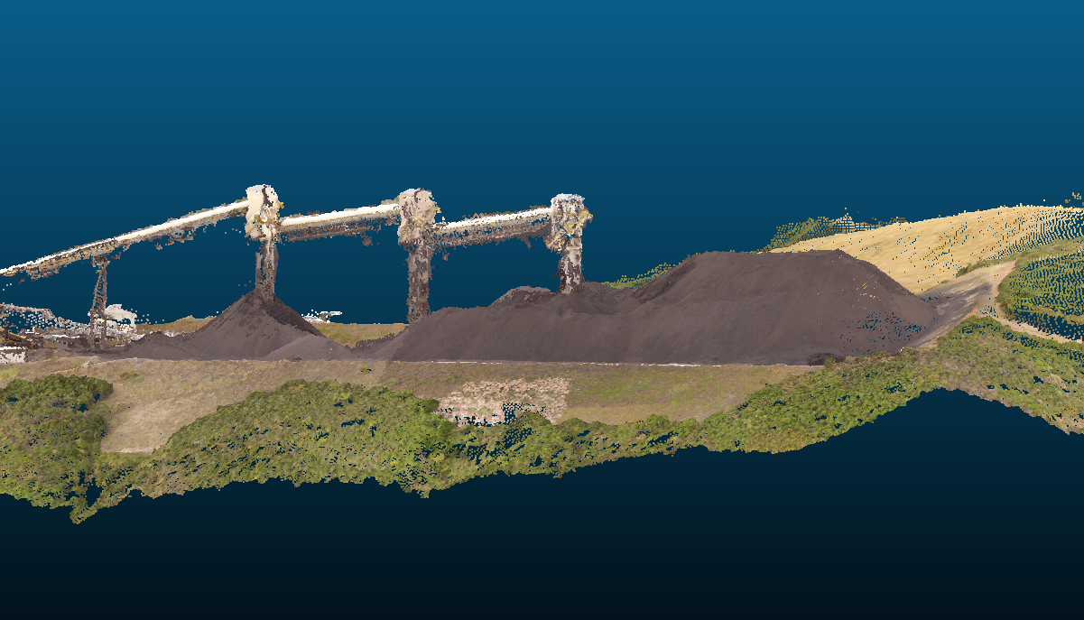

Figure 2: 3-D Model Rendering of Stockpiles – Conveyor Structures

The next illustration, Figure 3, shows the DEM of a portion of the stockpile along with the conveyor system overhead. The DEM/ortho processing was completed utilizing a GPU within one hour of imagery input. DEM resolution used was X4 of native imagery and ortho was X2. As a comparison Figure 4 illustrates the same section of DEM processed at a different time using only nadir images. Full native resolution was used in the processing of the nadir only images at that time as compared to Figure 3 processed with resolution scaling.
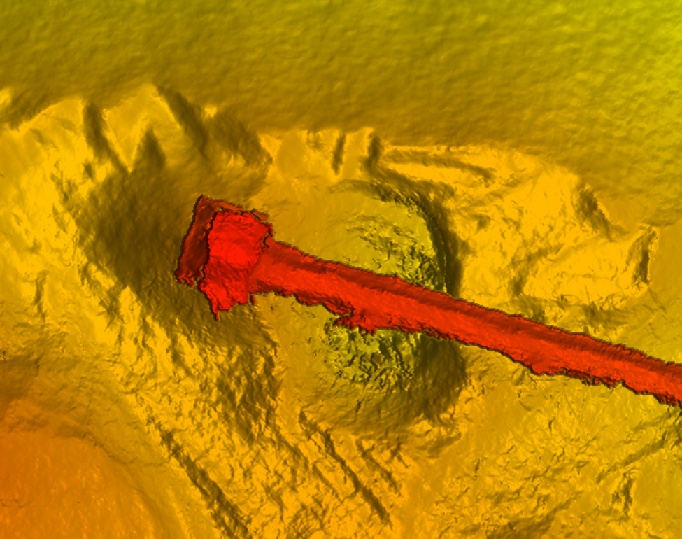

Figure 3: Nadir & Obliques – Section of DEM Showing Feature of Interest with Conveyor Overhead
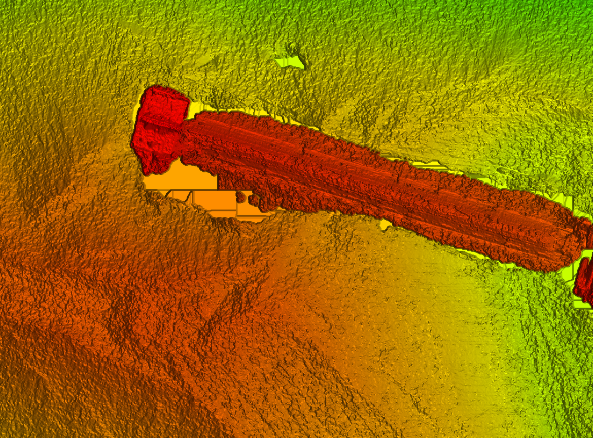

Figure 4: Nadir Only Images – Same Section of DEM with Conveyor Previously Processed

One can see the crispness of the structure (Figure 3) and lack of blobbing/noise (Figure 4) that the use of obliques contributes. This makes extraction of the structure and rendering of the surface below it cleaner with less surface errors that contribute to volumetric estimate inaccuracies. When the conveyor structure is carefully removed from the DEM an accurate rendering of the stockpile surface results as illustrated in Figure 6.
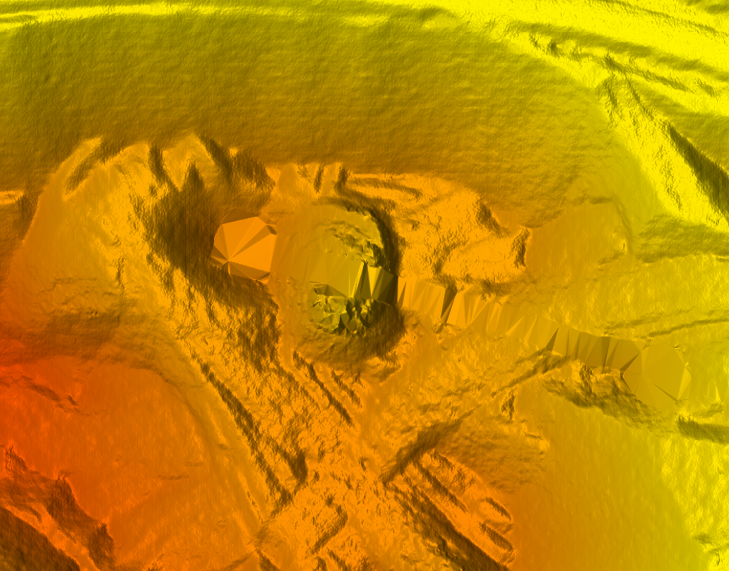

Figure 6: Stockpile Surface Model Suitable for Accurate Measurements



Benefits of Combining UAS Oblique & NADIR Aerial Imagery

JP Uncategorized

DroneMapper Labs: Benefits of Combining UAS Oblique & NADIR Aerial Imagery
Jon-Pierre Stoermer, CTO – DroneMapper.com


DrnMppr R&D Labs update!: We recently finished development on a photogrammetric workflow that combines oblique and NADIR collections into one automated processing pipeline. Below is a visual example of two different processing methods we’ve developed here at DroneMapper. The first method being the traditional NADIR processing and the second method adding in obliques of the same AOI. We used the outstanding MapPilot iOS application to perform the traditional grid collection over the AOI, while still in flight we switch to Litchi and complete 2-4 “orbit” mode oblique captures. We’ve found that by adding in the oblique imagery data, one can extract cleaner digital elevation information, model the sides of structures/vegetation more accurately, generate a true geo-referenced 3D model for CAD applications and more! We completed these R&D flights with our DJI Phantom 3 Advanced over the last month.

Additionally, we’ve implemented a full GPU pipeline for our processing chain! The examples below were processed on a NVIDIA GTX 580.


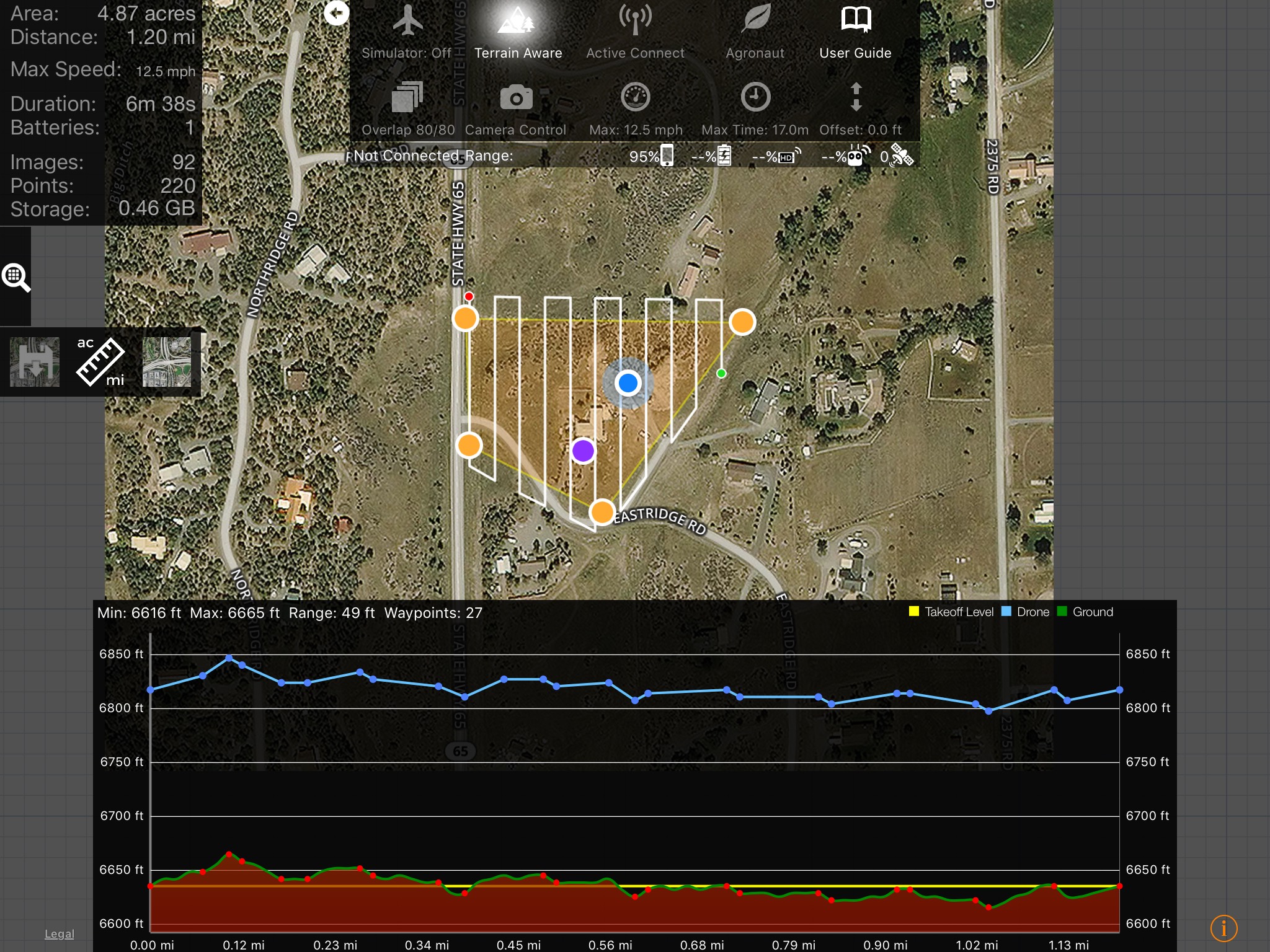
A grid flight pattern generated in MapPilot with terrain awareness.


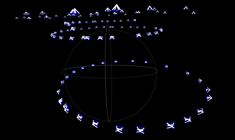
The camera poses for the oblique and NADIR collection.


A Colorado State Plane geo-referenced point cloud processed with NADIR imagery only.


Digital Elevation Model processed with only NADIR images in a traditional photogrammetric fashion.

From the previous two graphics, one can see that the DEM is constructed well but there is a considerable amount of structure and vegetation missing.


Digital Elevation Model processed with oblique and NADIR imagery from the DJI Phantom 3.


An example of an Orthomosaic generated from oblique and NADIR imagery with a NADIR score calculation on each pixel.


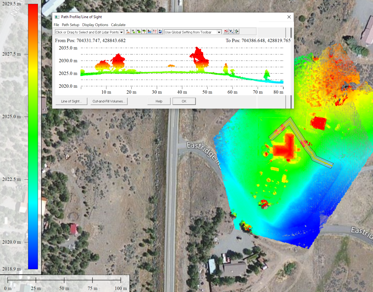
Elevation profile shown in Global Mapper for vegetation of interest.


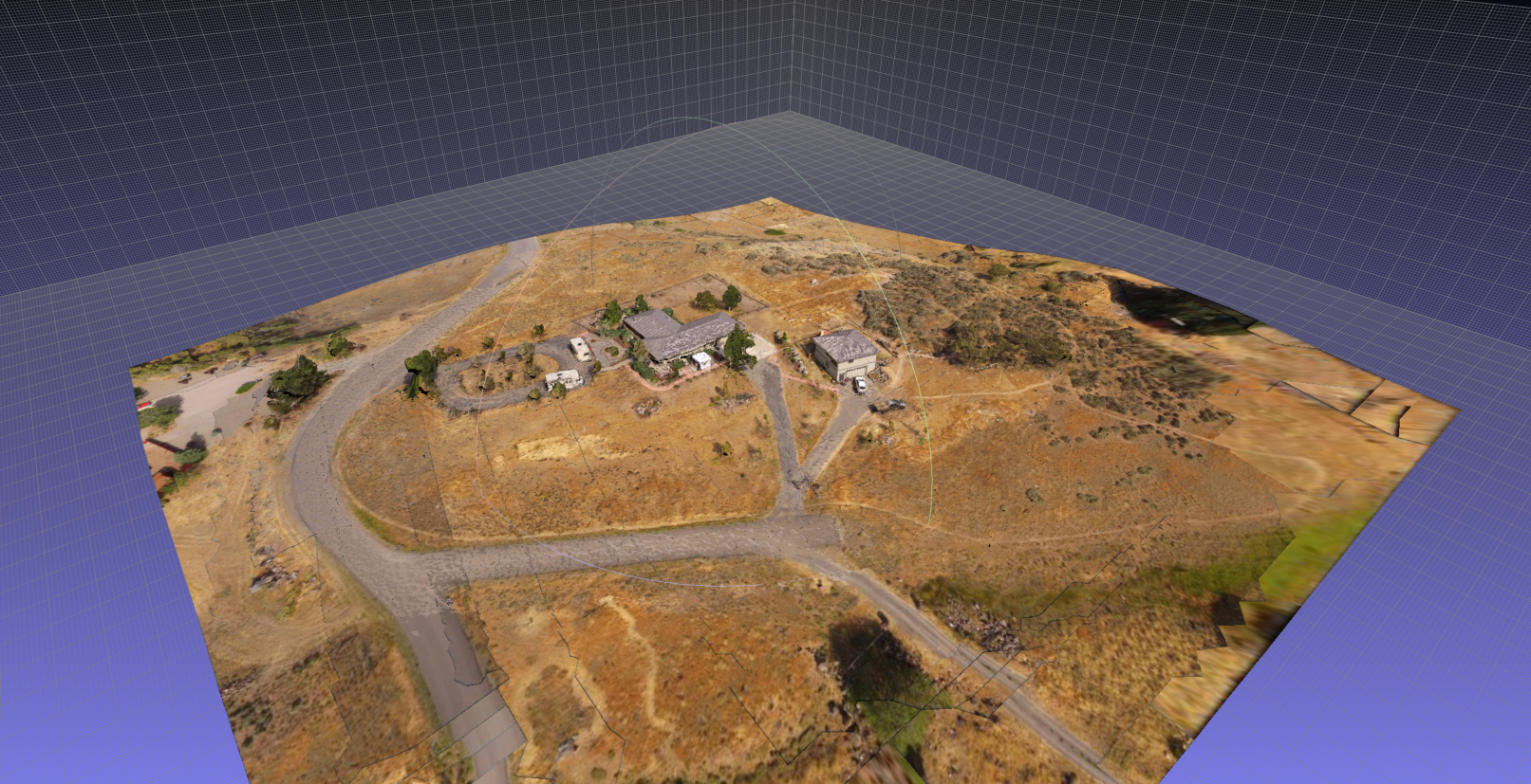
The final product: Geo-referenced textured mesh in Colorado State Plane projection viewed in MeshLab.


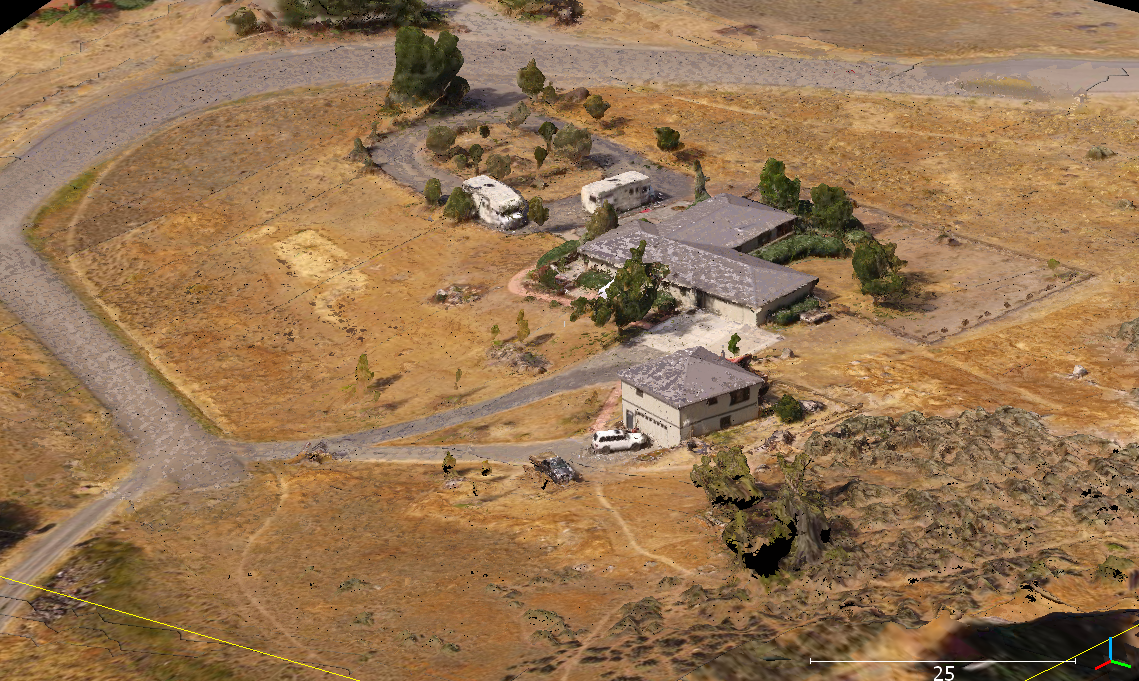
The final product: Geo-referenced textured mesh in Colorado State Plane projection viewed in CloudCompare 64bit.

So, how does it work? The short answer is we take the geo-referenced point clouds and generate a mesh. With a geo-referenced mesh we can then project the textures from required images onto the model.

Pretty cool. Let us know if you are interested in learning more!


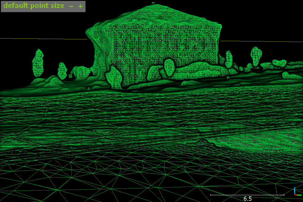
Geo-referenced wire-frame mesh.


An example of the images, orientations and textures for mesh construction.

DroneMapper Precision Mapping Session – DJI Phantom 3 & Inspire

JP Uncategorized

DroneMapper Precision Mapping Session – DJI Phantom 3 & Inspire
Pierre Stoermer, CEO – DroneMapper.com
 

Come join us for a 1-day interactive session and hands-on demonstrations of how to dial in your DJI platform for producing precision maps and valuable products for engineering, construction, mining, surveying and agricultural markets, amongst others. The session will be held in the town of Eckert (located on Hwy 65) on the south side of the beautiful Grand Mesa in Western Colorado. The fee for participants as well as the timing of the session in 2016 will be determined from responses to this post.

Envisioned Agenda (subject to participant's desires):

  • Introductions (8:00 to 8:15) –

  • Autonomous mission planning and execution (8:15 to 9:00) –

    • What applications? – DJI Go, DroneDeploy, MapPilot, Litchi, others

    • Area of Interest, Safety, Hazards, Weather, Platform capability

    • Ground Control?

    • Considerations for remote places

  • Platform set-up (9:00 to 9:15) –

    • Pre-mission checklist

    • Camera set-up and verification

  • At the Site (9:15 to 9:45) –

    • Pre-flight checklist

    • Ground control, imagery targets and surveying?

    • Flight operations

    • Hazard bail-out

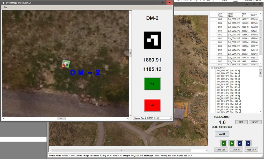
    • Post flight imagery quality assurance – DM QA/GCP tool, Geosetter

  • Abobe Buttes Mapping Flight (9:45 to 11:30) (weather permitting)

  • Lunch and discussion (11:45 to 12:45)

  • Imagery Processing (1:00 to 1:45)-

    • Do you really need the resolution you collected?

    • Control pre-processing

    • Rapid processing

    • Native resolution processing

    • File sizes – area and GSD

  • Post-processing – Global Mapper (1:45 to 2:30)

    • Visualization and analytics

    • Coordinate transformations

    • Exporting to CAD drawing formats

  • Abobe Buttes 3-D Modeling Flight (2:45 to 4:00) (weather permitting)

  • Open discussion (4:00 to 5:00)

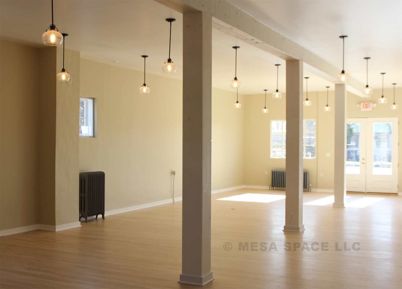
Class sessions will be held within the Mesa Space office building next to the Drost chocolate factory in Eckert. The Adobe Buttes area just north of Delta, CO, about 10 minutes from Eckert, will be used for mapping and 3-D modeling flight demonstrations. The Adobe's offer some very interesting topography, almost moon-like. You are welcome to bring your own DJI platform for complete set-up and participate in the autonomous collections.
 

If you have interest in the session please send Pierre an e-mail stating so (pierre@dronemapper.com), other session topics you would be interested in and the time frame you could attend. Thank you for your interest and feedback!
 

Mesa Space located in Eckert, Colorado MesaSpace.org