Pierre Stoermer, CEO – DroneMapper.com
This post addresses two topics 1) expected positional accuracy using ground control and 2) utilizing a combination of nadir and oblique images for optimal DEM construction.
Geo-spatial Accuracy:
Here we report on a set of recent imagery collections utilizing primarily UAV platforms (one manned platform included – Project L) with varied collection sensors. In each case well surveyed ground control was used in the processing of the DEM and orthomosaic. In each of the DEM/ortho sets the position of the control was compared to the surveyed coordinates to compute horizontal and vertical root mean square errors (RMSEs). All measurements were accomplished utilizing Global Mapper, version 16.2. The table below illustrates seven data sets with RMSEs computed.
Examples of DroneMapper Ortho & DM Ground Control Geo-spatial Errors (RMSE)
| Project | Scene Area (sq. Km) | GCP Number | Imagery GSD (cm) | Camera Used | Average Horizontal Error (RMSE – cm) | Vertical Error (RMSE – cm) |
| L | 180 | 27 | 14 | UltraCam Falcon prime | 2.85 | 7.9 |
| B | 1.15 | 22 | 3 | Sony a5100 | 1.3 | 3.5 |
| CB | 0.56 | 7 | 4.7 | DJI FC-300 | 3.2 | 3.6 |
| WE | 0.66 | 8 | 5.9 | Sony NEX-5R | 4.34 | 5.21 |
| TB-1 | 0.56 | 5 | 5.6 | DJI FC-350 | 2.3 | 3.3 |
| TB-2 | 0.94 | 5 | 7.4 | DJI-FC-350 | 3.6 | 4.66 |
| McB | 0.88 | 7 | 6.2 | DJI FC-300X | 2.2 | 5.2 |
The data sets include a manned aircraft using Vexcel’s UltraCam Falcon prime (Project L), two fixed wing UAVs using Sony cameras (Projects B and WE) and four DJI quad-copter UAVs using the FC series of sensors (Projects CB, TB-1, TB-2 and McB). In all cases except one, Project B – vertical error, the horizontal and vertical RMSEs are sub-pixel (compared to the native GSD).
When we average the four DJI project horizontal and vertical errors as a percentage of GSD we see that one could expect an error of one-half pixel horizontal and three-quarters pixel vertical. In terms of absolute map accuracy with 95% confidence one could expect 1.2 pixels horizontal and 1.5 pixels vertical. So for you DJI operators, if your application requires absolute vertical accuracy of 3”, plan on imaging at 2” pixel GSD or less with well surveyed control.
Nadir and Obliques for DEM Construction:
A set of nadir and oblique images were collected for a mining operation, interested in accurate volumetric estimation. The accuracy of the estimate is dependent on the pile size and vertical error. We used a DJI Phantom 3 flying at an AGL of approximately 200’ (GSD: ~ 1”). Four (4) existing ground control points (GCP) were utilized for precise geo-referencing of the ortho and DEM. An example GCP from the ortho along with the ground truth position (black labeled dot) is illustrated in Figure 1.
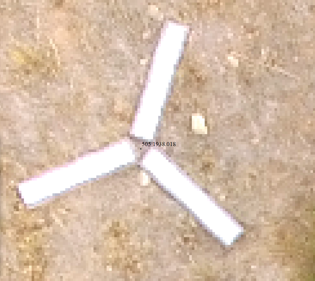
Figure 1: Typical Ground Control Point
In this case, GCPs are used for referencing the stockpile surface to a bare ground DTM in order to accurately measure temporal changes. The mining operation utilizes an above pile conveyor system for stockpile distribution. For traditional nadir only image collections the conveyor obscures the pile surface, making accurate surface definition below it difficult. We utilized both nadir and oblique images in order to see the pile surface that is typically obscured with nadir only images. Figure 2 shows a point cloud of one of the stockpiles along with the conveyor structures overhead.
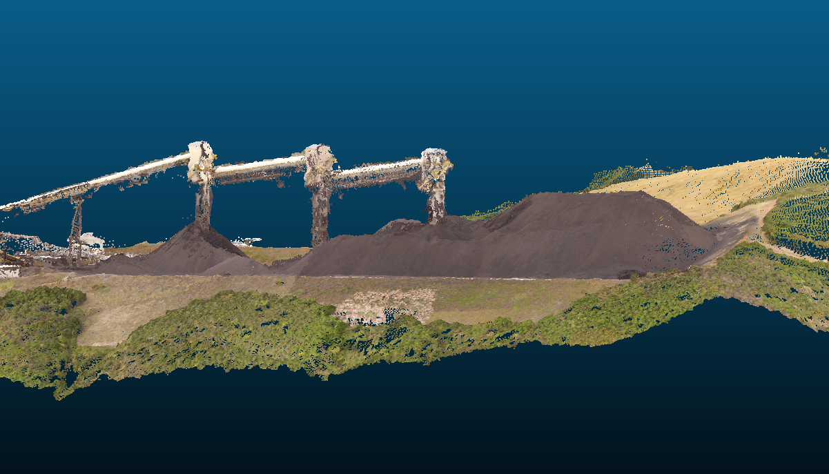
Figure 2: 3-D Model Rendering of Stockpiles – Conveyor Structures
The next illustration, Figure 3, shows the DEM of a portion of the stockpile along with the conveyor system overhead. The DEM/ortho processing was completed utilizing a GPU within one hour of imagery input. DEM resolution used was X4 of native imagery and ortho was X2. As a comparison Figure 4 illustrates the same section of DEM processed at a different time using only nadir images. Full native resolution was used in the processing of the nadir only images at that time as compared to Figure 3 processed with resolution scaling.
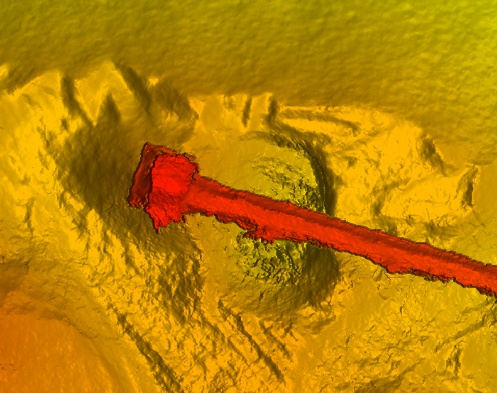
Figure 3: Nadir & Obliques – Section of DEM Showing Feature of Interest with Conveyor Overhead
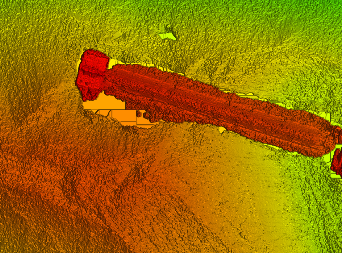
Figure 4: Nadir Only Images – Same Section of DEM with Conveyor Previously Processed
One can see the crispness of the structure (Figure 3) and lack of blobbing/noise (Figure 4) that the use of obliques contributes. This makes extraction of the structure and rendering of the surface below it cleaner with less surface errors that contribute to volumetric estimate inaccuracies. When the conveyor structure is carefully removed from the DEM an accurate rendering of the stockpile surface results as illustrated in Figure 6.
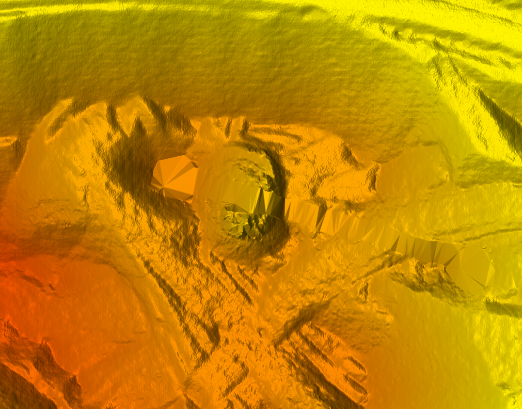
Figure 6: Stockpile Surface Model Suitable for Accurate Measurements