Jon-Pierre Stoermer, CTO – DroneMapper.com
DrnMppr R&D Labs update!: We recently finished development on a photogrammetric workflow that combines oblique and NADIR collections into one automated processing pipeline. Below is a visual example of two different processing methods we’ve developed here at DroneMapper. The first method being the traditional NADIR processing and the second method adding in obliques of the same AOI. We used the outstanding MapPilot iOS application to perform the traditional grid collection over the AOI, while still in flight we switch to Litchi and complete 2-4 “orbit” mode oblique captures. We’ve found that by adding in the oblique imagery data, one can extract cleaner digital elevation information, model the sides of structures/vegetation more accurately, generate a true geo-referenced 3D model for CAD applications and more! We completed these R&D flights with our DJI Phantom 3 Advanced over the last month.
Additionally, we’ve implemented a full GPU pipeline for our processing chain! The examples below were processed on a NVIDIA GTX 580.
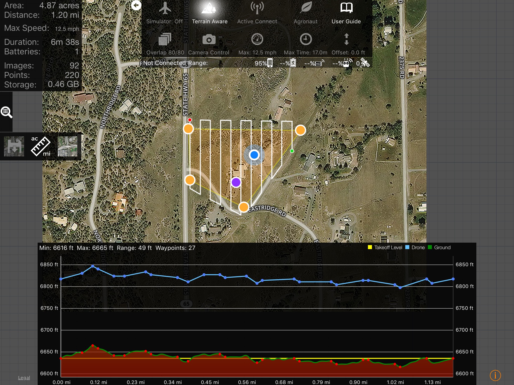
A grid flight pattern generated in MapPilot with terrain awareness.
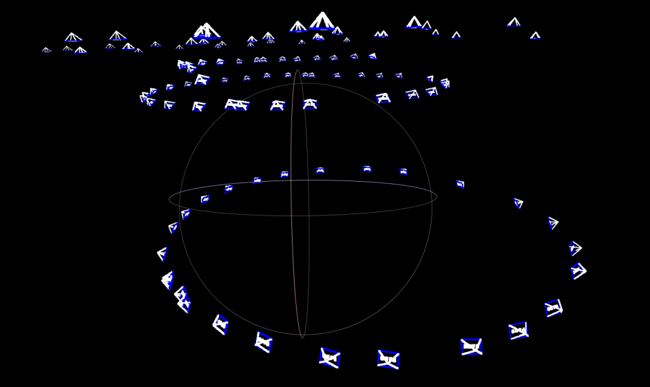
The camera poses for the oblique and NADIR collection.
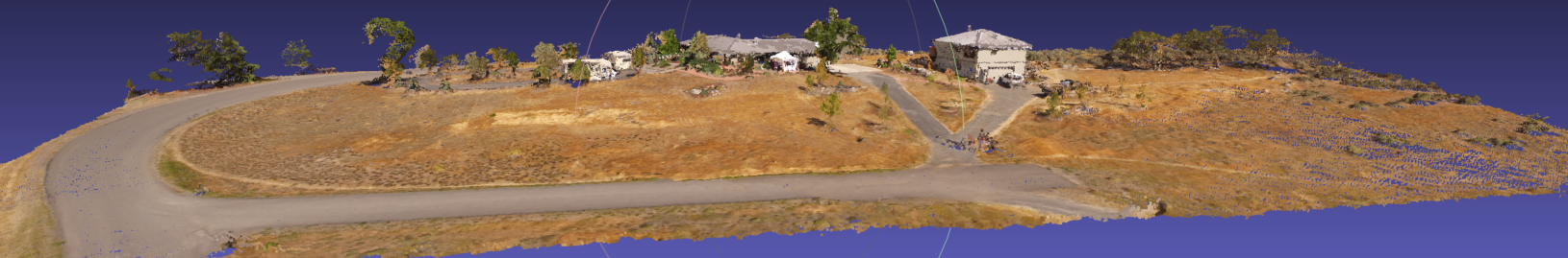
A Colorado State Plane geo-referenced point cloud processed with NADIR imagery only.
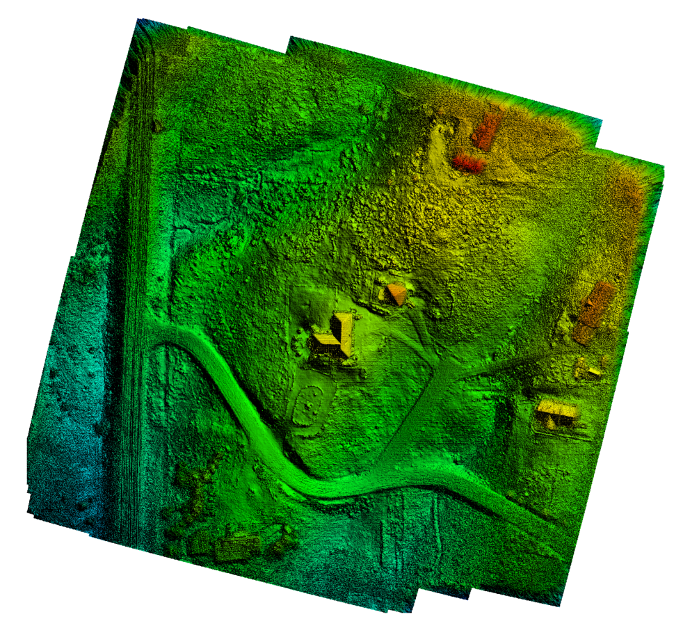
Digital Elevation Model processed with only NADIR images in a traditional photogrammetric fashion.
From the previous two graphics, one can see that the DEM is constructed well but there is a considerable amount of structure and vegetation missing.
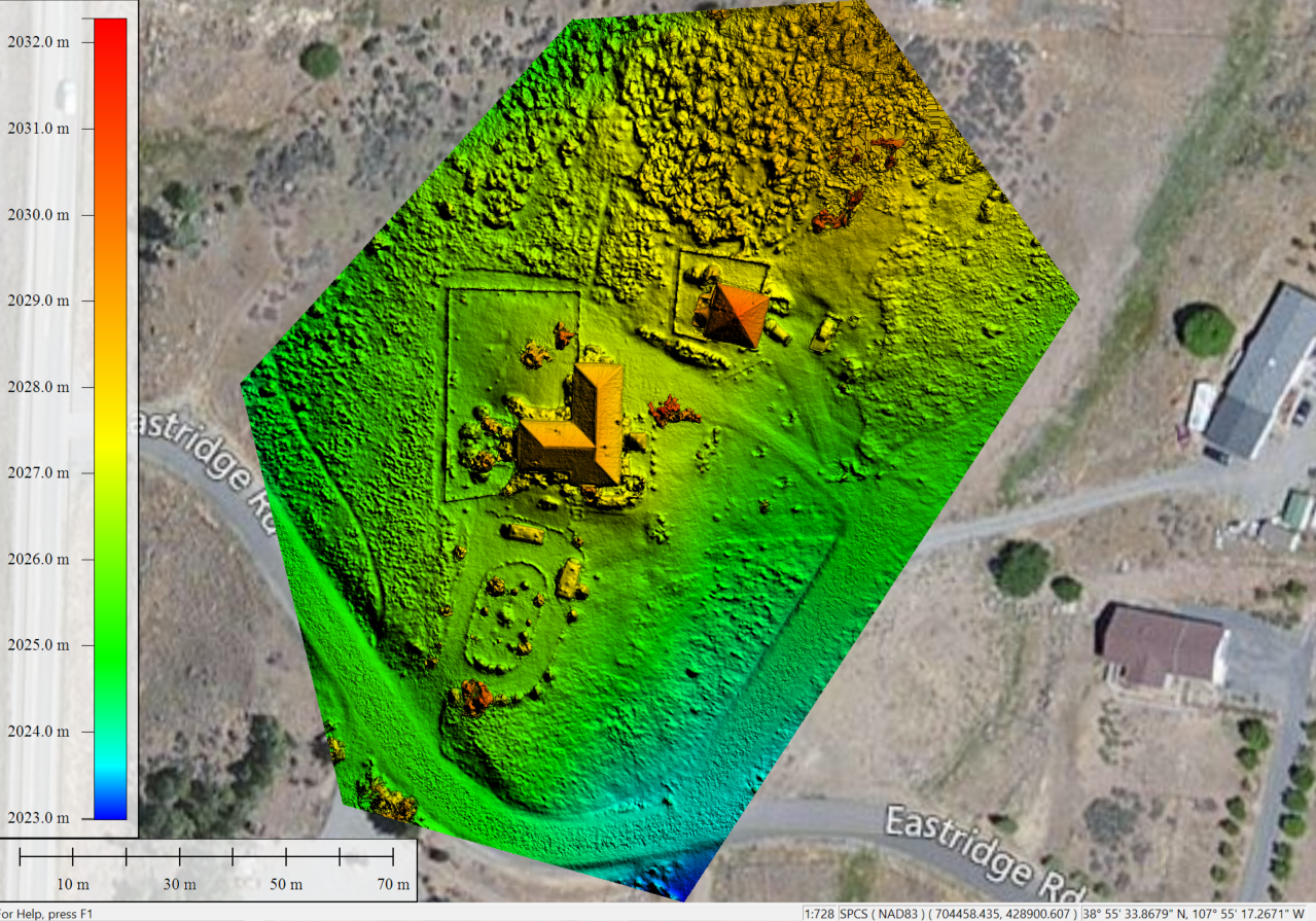
Digital Elevation Model processed with oblique and NADIR imagery from the DJI Phantom 3.
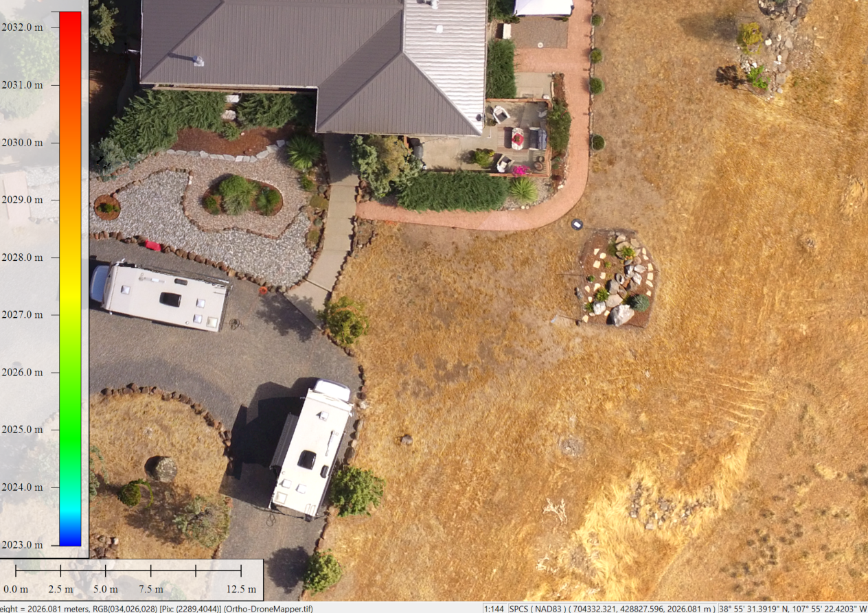
An example of an Orthomosaic generated from oblique and NADIR imagery with a NADIR score calculation on each pixel.
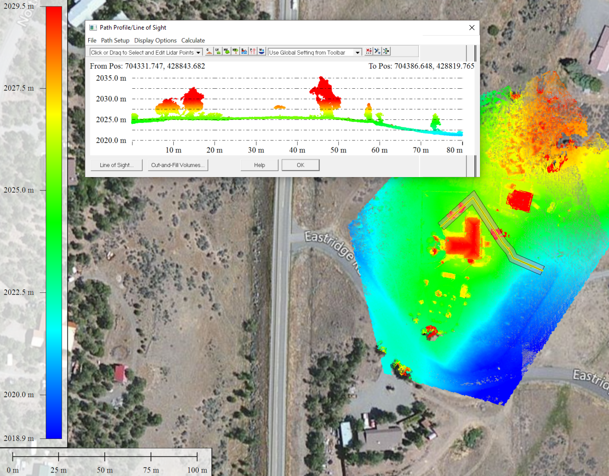
Elevation profile shown in Global Mapper for vegetation of interest.
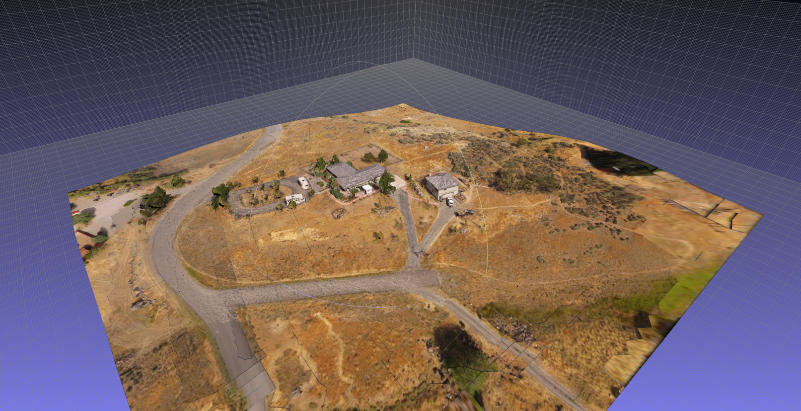
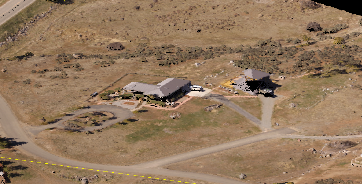
The final product: Geo-referenced textured mesh in Colorado State Plane projection viewed in MeshLab.
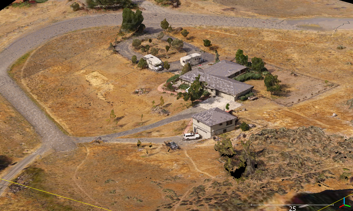
The final product: Geo-referenced textured mesh in Colorado State Plane projection viewed in CloudCompare 64bit.
So, how does it work? The short answer is we take the geo-referenced point clouds and generate a mesh. With a geo-referenced mesh we can then project the textures from required images onto the model.
Pretty cool. Let us know if you are interested in learning more!
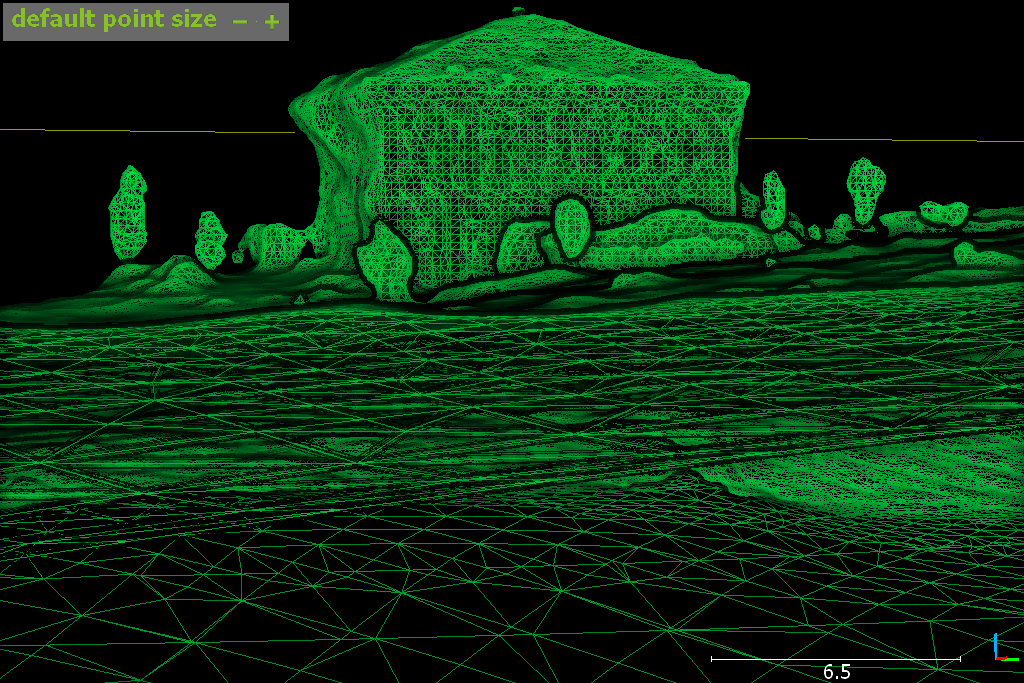
Geo-referenced wire-frame mesh.
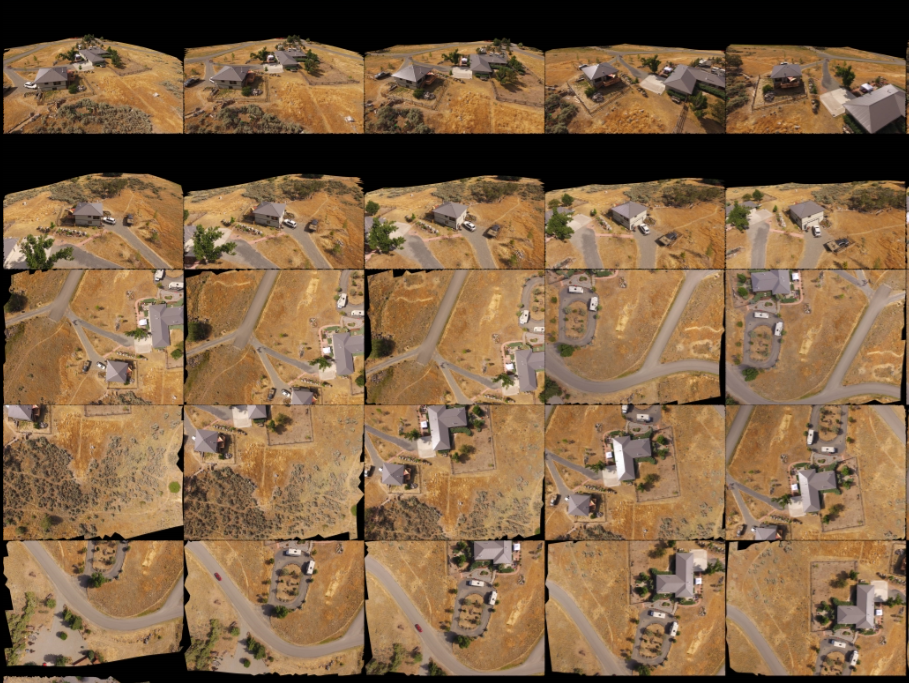
An example of the images, orientations and textures for mesh construction.